Deep Sea Electronics DSE6120 MKIII
Single-generator AMF controller
DSE6120 MKIII adds mains supervision to the DSE6100 MKIII single-generator family. It supports electronic and non-electronic engines and provides USB configuration. Its DSENet expansion connection should not be mistaken for an open Modbus RTU monitoring port.
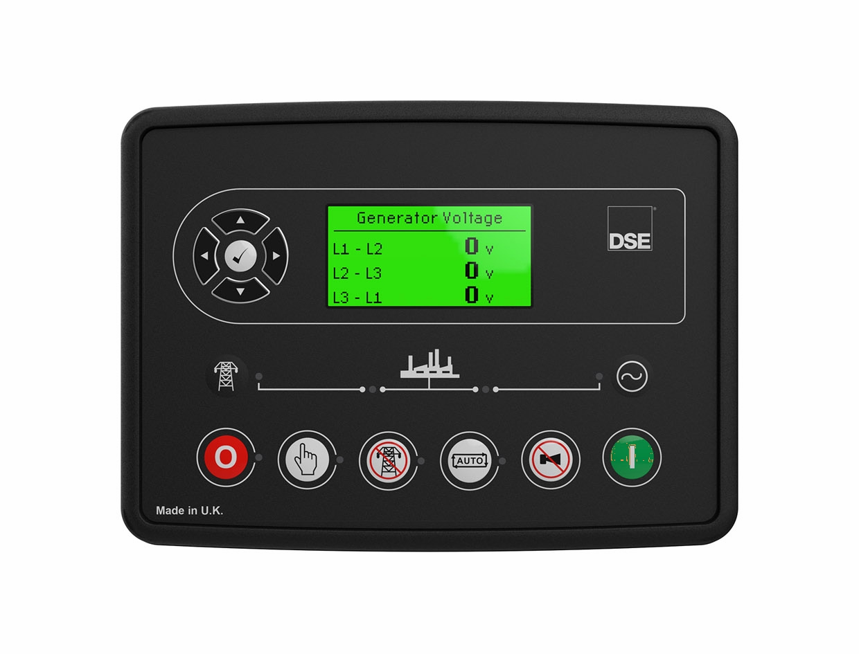
Single-generator AMF controller
Compatibility
Controller selection and monitoring options
USB configuration port, CAN engine link and DSENet expansion; no documented RS-485 Modbus port
DSE6120 MKIII is the AMF model; DSE6110 MKIII is auto start. MKIII documentation does not establish the serial or Ethernet interfaces of DSE7320 or DSE8620 models.
Models
| Models | Interface | Route into Edge |
|---|---|---|
| DSE6120 MKIII | USB configuration port, CAN engine link and DSENet expansion; no documented RS-485 Modbus port | Save the DSE Configuration Suite file over USB and identify the configured engine and mains measurements. For a BMS or Edge project, choose separate electrical metering and status contacts where the existing panel exposes them, or use a controller with a published communications interface. |
Specifications
DSE6120 MKIII is the AMF model; DSE6110 MKIII is auto start. MKIII documentation does not establish the serial or Ethernet interfaces of DSE7320 or DSE8620 models.12
- Plant role
- Single-generator AMF controller1
- Monitoring and configuration
- USB configuration port, CAN engine link and DSENet expansion; no documented RS-485 Modbus port2
- Model distinction
- DSE6120 MKIII is the AMF model; DSE6110 MKIII is auto start. MKIII documentation does not establish the serial or Ethernet interfaces of DSE7320 or DSE8620 models.12
- Panel protection
- IP65 front when correctly panel-mounted with the specified gasket. Check whether the gasket is supplied or an option for the exact model.2
Interface
Documented measurements and integration boundaries for DSE6120 MKIII.
- Generator electrical measurements and mains supply status on the display
- Engine speed, operating state and configured analogue or ECU measurements
- Alarm and output indications from the existing controller application
Assessment
USB configuration port, CAN engine link and DSENet expansion; no documented RS-485 Modbus port
- InteroperabilityNot yet assessed
- USB configuration port, CAN engine link and DSENet expansion; no documented RS-485 Modbus port
- AccuracySupported with conditions
- The documentation identifies electrical and operating measurements for this plant role. CT configuration and measurement location determine how those values are used.12
- SecurityNot yet assessed
- The cited documentation does not establish an authenticated, encrypted Edge monitoring connection.
- ReliabilityNot yet assessed
- The controller application distinguishes operating conditions and alarms. Retain communication availability alongside the plant readings.
- RuggednessSupported with conditions
- IP65 front when correctly panel-mounted with the specified gasket. Check whether the gasket is supplied or an option for the exact model.2
- ScalabilityNot yet assessed
- Assign one device identity per controller and keep generator, mains and busbar measurements separate.
Setup
-
Save the DSE Configuration Suite file over USB and identify the configured engine and mains measurements.
For a BMS or Edge project, choose separate electrical metering and status contacts where the existing panel exposes them, or use a controller with a published communications interface.
-
Record CT ratios and the physical measurement location.
Compare the first electrical values with the controller display before using them in totals or trends.
-
Keep missing responses distinct from a stopped generator.
Store communication availability beside running state so a disconnected cable does not look like healthy standby.
Related devices
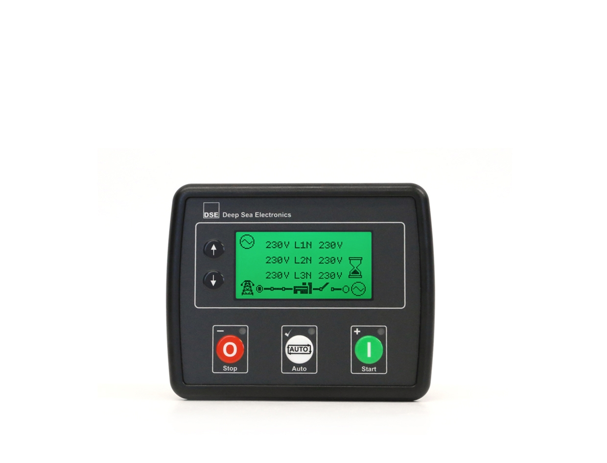
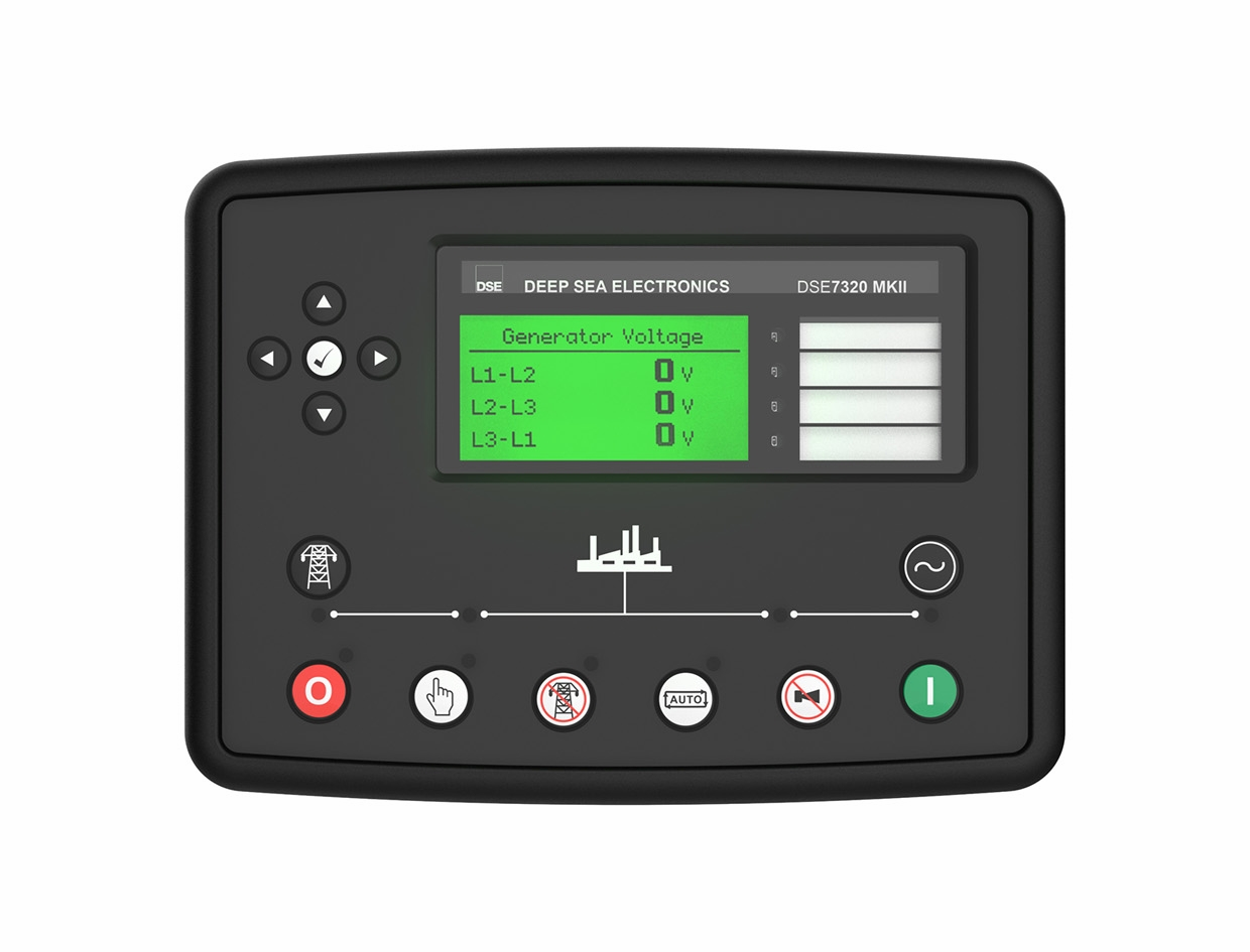
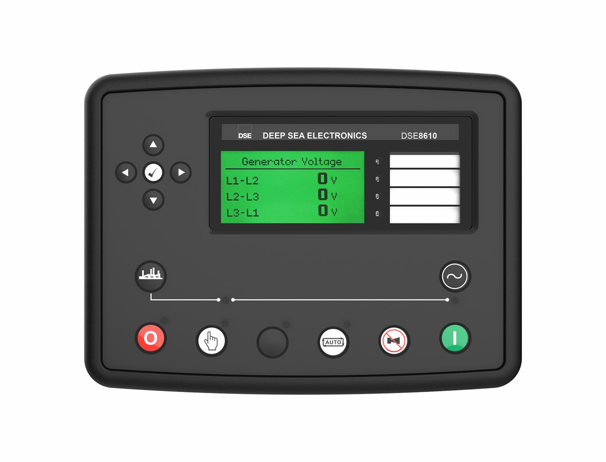
Similar devices
Sources
Further reading
Product names and trademarks belong to their owners. Publication does not imply endorsement or a commercial relationship.