SmartGen HGM7220N
Single-generator AMF controller
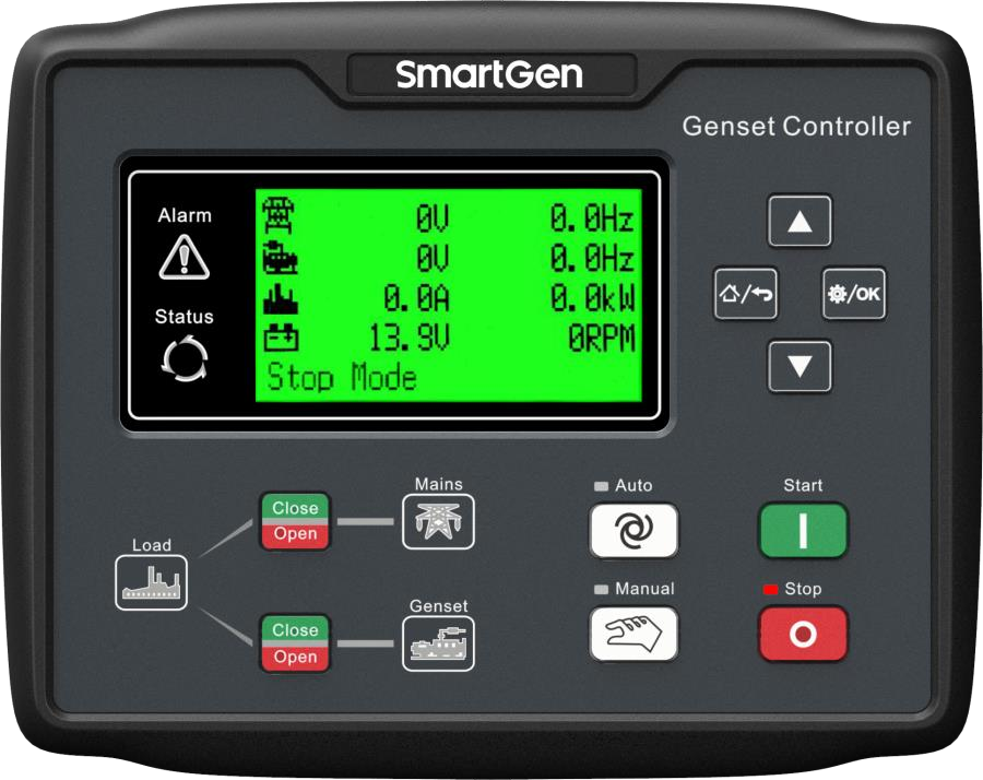
HGM7220N is a single-generator automatic mains-failure controller with RS-485 monitoring. SmartGen publishes its Modbus protocol, including individual alarm flags and scaled electrical measurements. HGM7220S adds synchronised changeover; the N and S roles should stay distinct in the plant inventory.
- Modbus RTU
Single-generator AMF controller
Compatibility
Documented Modbus RTU interface
RS-485 Modbus RTU; do not infer an Ethernet socket from cloud-monitoring accessories
The S variant supports synchronised changeover. A remote cloud module does not turn the N controller’s own RS-485 port into native Modbus TCP.
Connect it with
-
Modbus Interface ZMB-3XFrom €399 ex VAT Configure Modbus Interface
-
Gateway ZGW-20From €899 ex VAT Configure Gateway


When the documented monitoring interface is fitted and configured
- Modbus
- Edge
- Platforms
Models
| Models | Interface | Route into Edge |
|---|---|---|
| HGM7220N | RS-485 Modbus RTU; do not infer an Ethernet socket from cloud-monitoring accessories | Set the controller address and serial format to match the monitoring client. Use the HGM7220N/7220S protocol table for FC03 measurement reads, retain each unit and signedness, and compare voltage and frequency with the display before collecting longer trends. |
Specifications
The S variant supports synchronised changeover. A remote cloud module does not turn the N controller’s own RS-485 port into native Modbus TCP.12
- Plant role
- Single-generator AMF controller1
- Monitoring and configuration
- RS-485 Modbus RTU; do not infer an Ethernet socket from cloud-monitoring accessories2
- Model distinction
- The S variant supports synchronised changeover. A remote cloud module does not turn the N controller’s own RS-485 port into native Modbus TCP.12
- Panel protection
- Front panel IP65.1
Interface
Documented measurements and integration boundaries for HGM7220N.
- Generator and mains voltage, frequency and power values in the Modbus table
- Engine analogue measurements and operating state
- Separate alarm flags, breaker states and controller mode
Assessment
RS-485 Modbus RTU; do not infer an Ethernet socket from cloud-monitoring accessories
- InteroperabilitySupported with conditions
- RS-485 Modbus RTU; do not infer an Ethernet socket from cloud-monitoring accessories12
- AccuracySupported with conditions
- The documentation identifies electrical and operating measurements for this plant role. CT configuration and measurement location determine how those values are used.12
- SecurityNot yet assessed
- The cited documentation does not establish an authenticated, encrypted Edge monitoring connection.
- ReliabilityNot yet assessed
- The controller application distinguishes operating conditions and alarms. Retain communication availability alongside the plant readings.
- RuggednessSupported with conditions
- Front panel IP65.1
- ScalabilityNot yet assessed
- Assign one device identity per controller and keep generator, mains and busbar measurements separate.
Setup
Read generator frequency
Best-effort first read from HGM7220N/7220S protocol V1.2, 19 May 2025, page 18. Compare this value with the generator display before adding more points.
- Function
- 03, read holding registers; quantity 1
- Address convention
- Table 0084 / PLC reference 40085 means decimal PDU offset 84 (0x0054)
- Request PDU
- 03 00 54 00 01
- Decode
- Unsigned 16-bit value, 0.01 Hz per count. Example 0x1388 = 5000 = 50.00 Hz.
Acceptance: Compare with generator frequency, rather than mains frequency at offset 64.
-
Set the controller address and serial format to match the monitoring client.
Use the HGM7220N/7220S protocol table for FC03 measurement reads, retain each unit and signedness, and compare voltage and frequency with the display before collecting longer trends.
-
Record CT ratios and the physical measurement location.
Compare the first electrical values with the controller display before using them in totals or trends.
-
Keep missing responses distinct from a stopped generator.
Store communication availability beside running state so a disconnected cable does not look like healthy standby.
-
Build a read-only point list for monitoring.
Remote start, synchronisation and breaker operation require a separate control design with the existing panel interlocks and feedback.
Related devices
Sources
Further reading
Product names and trademarks belong to their owners. Publication does not imply endorsement or a commercial relationship.