Legionella temperature monitoring
Wireless pipe probes on the calorifier flow and return, the end of each loop and the cold feed. Edge trends every point and raises an alarm when a temperature drops or a sensor goes quiet.
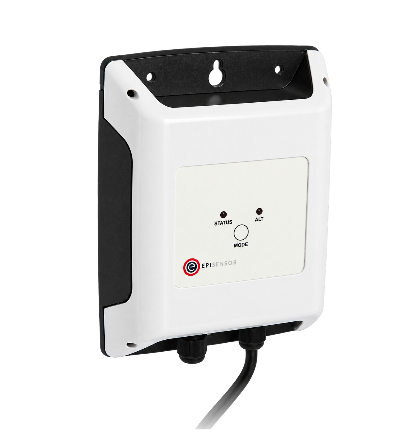

- Measure
- Calorifier flow and return, the return leg of each loop, the cold-water supply
- Good practice
- Calorifier flow 60 °C, return not below 50 °C HSG274
- Sensors
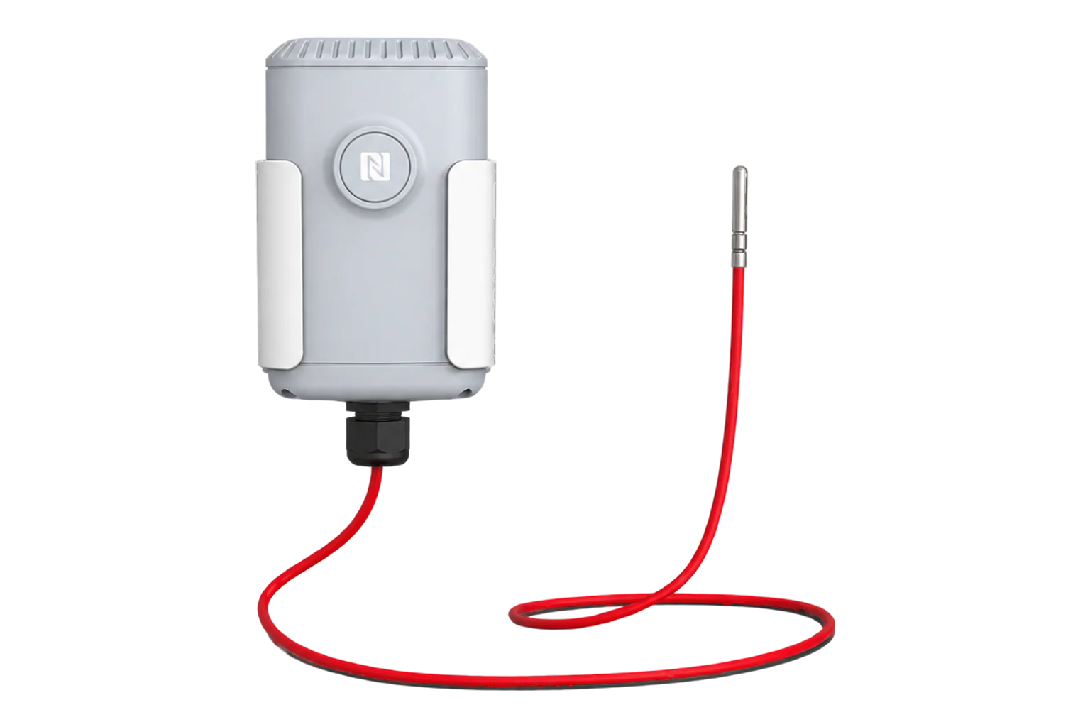
- TES-22 pipe probes, ±0.2 °C from 0 to 70 °C Probe Temperature Sensor datasheet
- On site
- ZGW-20 Gateway, up to 250 wireless devices Gateway datasheet
Hardware for hot water temperature monitoring
One TES-22 reads a calorifier's flow and return. Each other pipe you watch takes a TES-21, and one Gateway serves the site.
Calorifier flow and return
1 per calorifier flow and return
 2 steel pipe probes, 2 m leads
±0.2 °C from 0 to 70 °C, battery life up to 10 years at 15-minute reporting
The return leg at the end of each loop, and the cold-water supply
1 per point loop end or cold feed
- 1 steel pipe probe, 2 m lead
Collects every sensor and runs Edge on site: trends, alarm rules and the record
1 per site up to 250 wireless devices
If the plant has a controller with a register map

Reads calorifier setpoints and pump run state from a plant controller over Modbus RTU
1 per controller up to 30 registers
Sensor positions on a calorifier loop
Start from the risk assessment and the water-system schematic. The competent person names the sentinel points, and each probe answers a question about one of them.
From field measurement to Edge
Each field signal reaches its named EpiSensor interface, reports through the site Gateway and is handled locally in Edge.
- Wired
- Zigbee
- Edge
- Platforms
| Position | What it tells you | Reference | Sensor |
|---|---|---|---|
| Calorifier flow | Whether water leaves storage hot enough | 60 °C or above HSG274 | TES-22 (on this page), probe 1 |
| Calorifier return | Whether the circuit loses too much heat on the way round | Not below 50 °C HSG274 | TES-22 (on this page), probe 2 |
| End of each loop | The far sentinel: the return leg towards the end of each circulating loop | At least 50 °C, 55 °C in healthcare premises HSG274 | TES-21 (on this page), one per loop |
| Cold-water supply | Heat gained by the cold feed before it reaches the calorifier | Below 20 °C where possible HSE | TES-21 (on this page) |
Insulate over each pipe probe. HSG274 accepts surface readings on metallic return legs. Insulate over the probe so it follows the water, not the plant room.
Allow ±0.5 °C during disinfection. The pipe probe holds ±0.2 °C from 0 to 70 °C and ±0.5 °C up to 105 °C.
Keep the transmitter off hot metal. The sensor enclosure is rated to operate up to 55 °C. Mount it on a cooler surface and run the lead to the pipe.
Calorifier return temperature monitoring in Edge
Rules run on the Gateway itself and watch every probe at once.
- A return below its limit
- A limit rule on each return probe. Agree the limit and how long it must hold with the responsible person, so a short draw-off does not raise an alarm.
- A sensor that stops reporting
- A no-data rule fires when a probe has been silent for a set time, from one minute to a day, so a missing reading is never taken for a good one.
- Who is told
- Email, SMS, a webhook to the BMS or helpdesk, or an alert in Edge. Email and SMS need the Gateway's mail and SMS settings, and a connection to reach them.
- A record through an outage
- Each TES stores up to 70,000 readings in its own memory. During a bounded radio outage, that buffer can retain readings for later recovery; retention depends on the reporting interval, outage length and available capacity.
Commissioning checks
Do these before anyone relies on the trends, and repeat the last one when the system changes.
-
Every probe is on the schematic
Name each sensor in Edge after its point on the water-system schematic, and photograph the fitted probe under its insulation.
Pass when every sensor name matches a point on the current schematic.
-
Each probe agrees with a reference
With the loop at temperature, read a calibrated contact thermometer on the same pipe beside each probe.
Pass when each difference is inside the tolerance agreed with the responsible person, and recorded.
-
An alarm reaches a person
Add a test rule on one probe with a limit its live reading already breaches, then delete the rule.
Pass when the named recipient receives the message and acknowledges it.
-
A silent sensor is reported
Take the battery out of one TES for longer than the no-data rule's time.
Pass when the no-data alarm arrives and names that sensor.
-
Trends match the monthly checks
Compare a month of trends with the manual monthly temperature checks at the same points.
Pass when any consistent difference is explained and written into the record.
Limits of this measurement
Temperature monitoring shows how the system behaves between manual checks. It does not assess every Legionella risk.
- The risk assessment, the written control scheme and the responsible person.
- Water sampling and microbiological testing.
- Outlet checks. A probe on a pipe does not measure the water at a tap after one minute of running.
- Flushing of little-used outlets, cleaning and disinfection, and the records of that work.
- Scald protection. HSE sets separate requirements for thermostatic mixing valves in healthcare premises.
Sources
- Legionnaires' disease: technical guidance HSG274 Part 2 (opens in a new tab) (opens in a new tab) Health and Safety Executive
- Hot and cold water systems (opens in a new tab) (opens in a new tab) Health and Safety Executive
- Probe Temperature Sensor datasheet (opens in a new tab) EpiSensor. Specifications, ranges and ordering codes.
Related
Third-party devices for this application
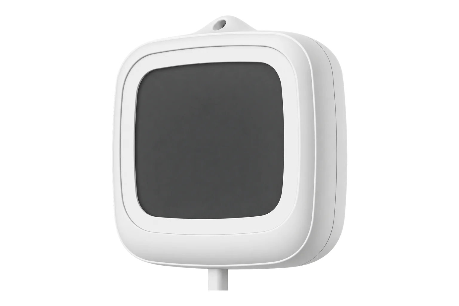
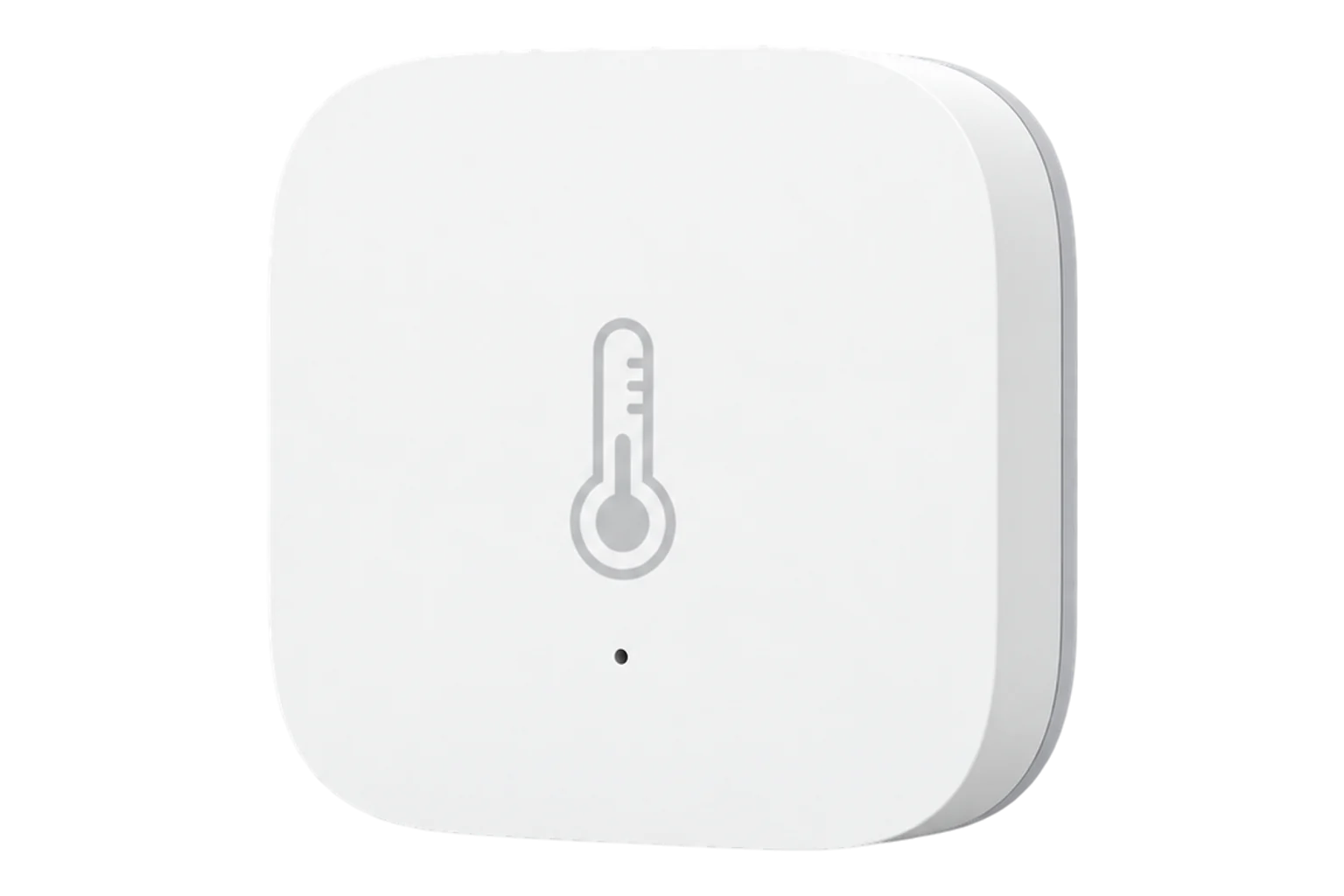
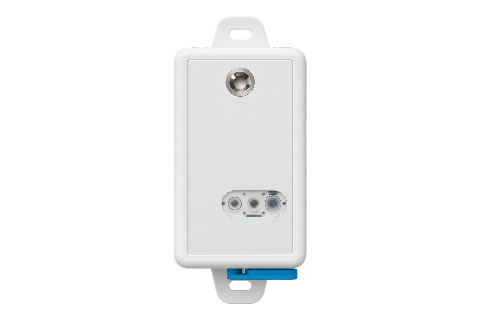
More in the Device Directory: Temperature and humidity sensors (21)
Put sensors where the risk assessment says they belong
An engineer can propose sensor positions against the risk assessment and size the sensors and Gateway for the site.