SmartGen HGM9510
Generator paralleling controller
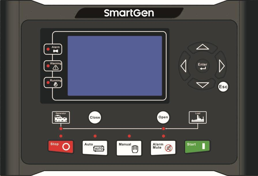
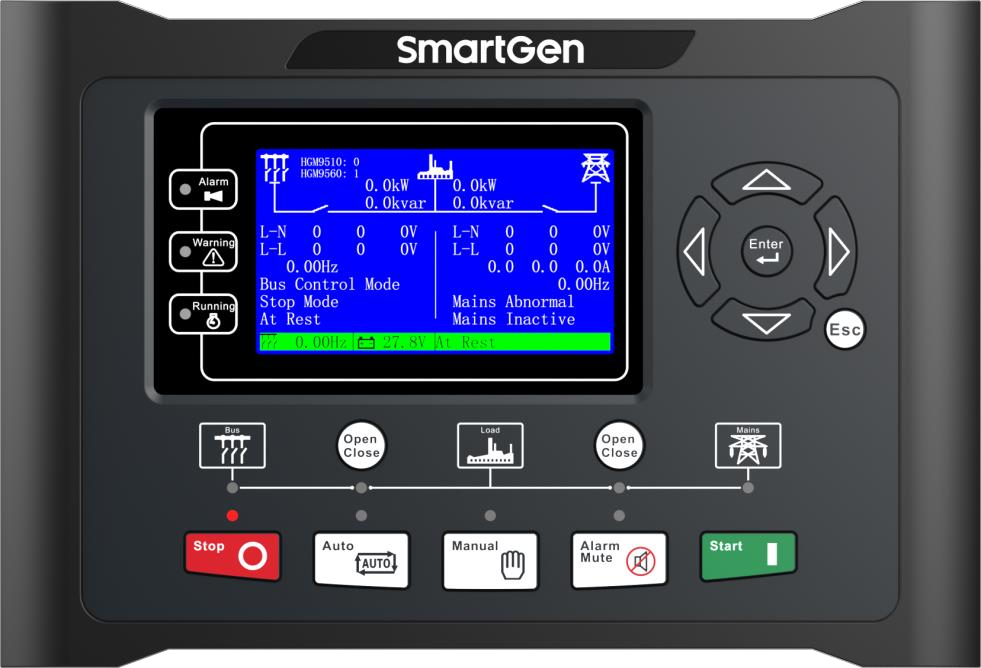
HGM9510 manages synchronisation and load sharing between generating sets. It exposes controller status and measurements through Modbus RTU. The published protocol provides a useful first read without changing the generator’s operating mode.
- Modbus RTU
Generator paralleling controller
Compatibility
Documented Modbus RTU interface
Two RS-485 Modbus RTU interfaces; CAN MSC is the separate generator coordination network
HGM9510 is the generator-paralleling controller. HGM9560 supervises mains and busbar switchgear. The MSC coordination bus is not the RS-485 Modbus monitoring segment.
Connect it with
-
Modbus Interface ZMB-3XFrom €399 ex VAT Configure Modbus Interface
-
Gateway ZGW-20From €899 ex VAT Configure Gateway


When the documented monitoring interface is fitted and configured
- Modbus
- Edge
- Platforms
Models
| Models | Interface | Route into Edge |
|---|---|---|
| HGM9510 | Two RS-485 Modbus RTU interfaces; CAN MSC is the separate generator coordination network | Record which RS-485 port serves monitoring and match its address and serial format. The protocol lists address 1 and 9600 baud with no parity and two stop bits as defaults. Begin with the status word at offset 0 before adding electrical readings. |
Specifications
HGM9510 is the generator-paralleling controller. HGM9560 supervises mains and busbar switchgear. The MSC coordination bus is not the RS-485 Modbus monitoring segment.12
- Plant role
- Generator paralleling controller1
- Monitoring and configuration
- Two RS-485 Modbus RTU interfaces; CAN MSC is the separate generator coordination network2
- Model distinction
- HGM9510 is the generator-paralleling controller. HGM9560 supervises mains and busbar switchgear. The MSC coordination bus is not the RS-485 Modbus monitoring segment.12
- Panel protection
- IP55 with the specified panel gasket.1
Interface
Documented measurements and integration boundaries for HGM9510.
- Generator electrical measurements and engine operating values in the protocol table
- Common alarm and operating-mode bits in the first status word
- Breaker and load-share application states
Assessment
Two RS-485 Modbus RTU interfaces; CAN MSC is the separate generator coordination network
- InteroperabilitySupported with conditions
- Two RS-485 Modbus RTU interfaces; CAN MSC is the separate generator coordination network12
- AccuracySupported with conditions
- The documentation identifies electrical and operating measurements for this plant role. CT configuration and measurement location determine how those values are used.12
- SecurityNot yet assessed
- The cited documentation does not establish an authenticated, encrypted Edge monitoring connection.
- ReliabilityNot yet assessed
- The controller application distinguishes operating conditions and alarms. Retain communication availability alongside the plant readings.
- RuggednessSupported with conditions
- IP55 with the specified panel gasket.1
- ScalabilityNot yet assessed
- Assign one device identity per controller and keep generator, mains and busbar measurements separate.
Setup
Read the controller status word
Best-effort starting point from the retained SmartGen protocol. Confirm the serial settings and compare this first read with the controller display.
- Source
- HGM9510 protocol, first FC03 status register
- Function
- 03, read holding registers; quantity 1
- Address convention
- Table 0000 / reference 40001 means PDU offset 0
- Request PDU
- 03 00 00 00 01
- Decode
- One 16-bit bitfield. Bit 0 is common alarm; bit 9 is Auto, bit 10 Manual and bit 11 Stop. Decode bits independently.
Acceptance: Compare the mode bits with the selected front-panel mode and retain the common-alarm bit as an independent status.
-
Record which RS-485 port serves monitoring and match its address and serial format.
The protocol lists address 1 and 9600 baud with no parity and two stop bits as defaults. Begin with the status word at offset 0 before adding electrical readings.
-
Record CT ratios and the physical measurement location.
Compare the first electrical values with the controller display before using them in totals or trends.
-
Keep missing responses distinct from a stopped generator.
Store communication availability beside running state so a disconnected cable does not look like healthy standby.
-
Build a read-only point list for monitoring.
Remote start, synchronisation and breaker operation require a separate control design with the existing panel interlocks and feedback.
Related devices
Sources
Further reading
Product names and trademarks belong to their owners. Publication does not imply endorsement or a commercial relationship.