Sinexcel PWS1-500KTL
Bidirectional battery storage inverter
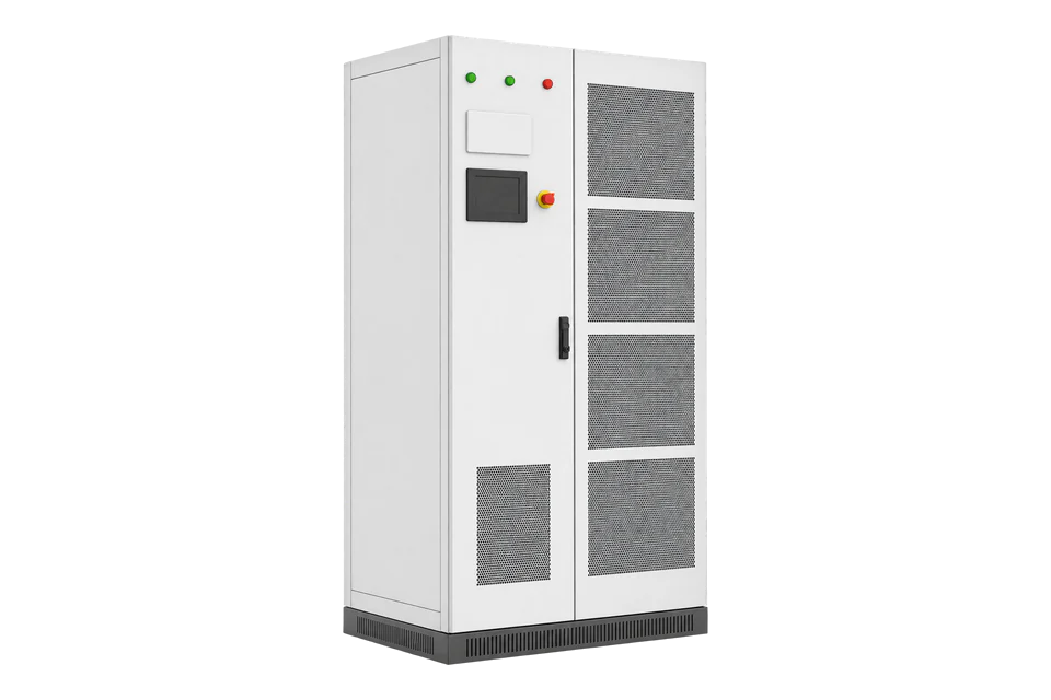
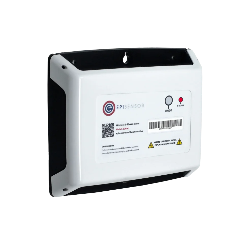
The Sinexcel PWS1-500KTL is a modular bidirectional power conversion system of 62.5 to 500 kVA, built from one to eight 62.5 kW power modules in one floor-standing cabinet, for one, four or eight battery strings. Its EMS interface is Modbus RTU on RS-485 by default or Modbus TCP on Ethernet, described by Sinexcel as compatible with SunSpec and MESA. Sinexcel does not publish the register map; Edge reads the PCS from Sinexcel's protocol document, or measures it with an EpiSensor ZEM on its AC feeder.
Compatibility
Compatible with EpiSensor Edge over Modbus TCP or Modbus RTU, with Sinexcel's PCS protocol document
The PWS1-500K series manual V4.0 states that the PCS supports Modbus over RS-485 and Ethernet for remote signalling and metering, with Modbus RTU on RS-485 as the default EMS link and Modbus TCP/IP on the touch screen's Ethernet port. Edge is a Modbus TCP and Modbus RTU client. The addresses, types and scales come from Sinexcel's PCS communication protocol for the installed firmware, which is not on the public download page.
PWS1-500KTL-EX and -NA without STS, power codes 1M1 to 8M1 in manual V4.0 and string variants 8M1, 8M4 and 8M8 in the 5 September 2025 datasheet. Site check: obtain Sinexcel's protocol document for the installed firmware, read operating status and total active power, and compare them with the touch screen AC Info page. Keep the site EMS as the only controller. Read-only monitoring; active power, reactive power, DC current and start or stop commands are out of scope.
Connect it with


When the EMS uses RS-485 or another interface and the PCS Ethernet port can join the protected site network
- Modbus
- Edge
- Platforms
When the RS-485 port is free, or when Edge is the site's monitoring master and no EMS uses the port
- Modbus
- Wireless
- Edge
- Platforms
When no protocol document is available, or for an independent measurement of charge and discharge at the AC connection
- Wired
- Edge
- Platforms
Models
| Models | Interface | Route into Edge |
|---|---|---|
| PWS1-500KTL-EX/NA-1M1 to -8M1 | One to eight 62.5 kW power modules: 62.5, 125, 187.5, 250, 312.5, 375, 437.5 or 500 kVA nominal, without isolation transformer and without STS | Modbus TCP or Modbus RTU with Sinexcel's protocol document; confirm the module count on the HMI Status page. |
| PWS1-500KTL-EX-8M4 and -8M8 | 500 kVA with four or eight independent battery strings (216 A or 108 A per branch) | Read each string's DC values from the protocol document's per-string points where the firmware provides them. |
| PWS1-500KTL with STS, PWS1-500K with transformer, PWS1-135M, PWS1-160M and PWS2-30P | Other Sinexcel PCS products with their own manuals | Do not transfer this guide's model scope; obtain the matching manual and protocol document. |
Specifications
The PWS1-500KTL is a non-isolated, three-phase, three-wire PCS for 600 to 900 V DC batteries. Its power scales from 62.5 kW to 500 kW with one to eight power modules, and the datasheet offers one, four or eight battery strings. It runs grid-tied or stand-alone; off-grid parallel operation of several PCS is a customised function.12
- Power
- 500 kVA nominal and 550 kVA maximum for 8 modules, in 62.5 kVA steps down to 62.5 kVA for 1 module12
- AC connection
- 3-phase 3-wire, 400 V (-15% to +15%) grid-tied; 380 / 400 V (±10%, configurable) stand-alone; 50 / 60 Hz (±2.5 Hz)2
- Battery
- 600 to 900 V DC; 864 A maximum DC current at 500 kVA with one string, 216 A per branch with four strings, 108 A per branch with eight2
- Communication
- RS-485, CAN and Ethernet; EMS on Modbus RTU (default) or Modbus TCP/IP, compatible with SunSpec/MESA; BMS on CAN by default1
- EMS timing
- Modbus data queries more than 500 ms apart; regular parameter and command interval more than 1 s1
- Serial settings
- Modbus address 1 to 247; RTU baud rate 19200 or 96001
Interface
Documented measurements and integration boundaries for PWS1-500KTL.
- Sinexcel's public documents give no register addresses. Take addresses, function codes, data types, scales and word order from Sinexcel's PCS communication protocol for the installed firmware, and ask which SunSpec or MESA models it serves.
- The touch screen AC Info page shows per-phase voltage, current, P, Q, S and PF, total P, Q and S, frequency, and charged and discharged energy in kWh. Use these as the reference set when choosing points from the protocol document, and compare each one with the page.
- The DC Info page shows DC voltage, current, power, status, warning, switch state and bus voltage. On 8M4 and 8M8 cabinets, read each battery string separately.
- The Status page shows the version and status of each AC and DC module; read the operating state and active warnings so a stopped module is not reported as zero power.
- BMS values come over CAN through the PCS and vary by battery brand. Read them only where the protocol document maps them, and keep the BMS as the authority on cell data.
- Smart meters, air conditioning, fire fighting, water level and diesel generators connect to the external EMS, not to the PCS. Read them from their own devices or the EMS.
- No active power, reactive power, power factor, DC current, DC power or start and stop setpoint is read back into control. Writes stay with the site EMS.
Assessment
PWS1-500KTL-EX and -NA without STS, read-only over Modbus TCP or Modbus RTU with Sinexcel's protocol document, or by an EpiSensor ZEM on the AC feeder.
- InteroperabilityLimited
- The manual documents Modbus RTU and Modbus TCP, the ports, the address and baud-rate settings and SunSpec/MESA compatibility. The register map itself is not public and comes from Sinexcel per firmware.1
- AccuracyLimited
- The touch screen shows per-phase and total AC quantities, charged and discharged energy and DC values, so the PCS holds a useful point set. Their register types, resolution and accuracy are not in the public documents.1
- SecurityLimited
- The touch screen has hierarchical passwords, but the manual prints the default administrator password and documents no authentication on Modbus. The same interface carries EMS control, so the network must be segregated.1
- ReliabilitySupported with conditions
- The datasheet lists protections, overload capability and certifications, and the manual states the query and command timing the PCS expects. Client recovery after a communication loss is not described.12
- RuggednessSupported with conditions
- The standard cabinet is IP20 / NEMA 1 for indoor or containerised installation, with an optional IP54 outdoor cabinet; temperature, humidity and altitude limits are published.23
- ScalabilitySupported with conditions
- Modbus addresses run from 1 to 247 and each cabinet has its own IP address, so several PCS cabinets can be read on one network. The number of simultaneous Modbus TCP clients is not published.1
Setup
-
Record the cabinet and its controller
Read the type label for the full model code, including module count and string variant. Record the PCS firmware, the battery and BMS brand, and the EMS that controls the PCS and which port it uses.
-
Obtain the protocol document
Ask Sinexcel or the system integrator for the PWS1-500KTL Modbus communication protocol that matches the installed firmware. Ask which SunSpec or MESA models it implements and at which base address, and whether the Ethernet port accepts a second Modbus TCP client alongside the EMS.
-
Choose a port that does not disturb the EMS
If the EMS uses the RS-485 terminals, connect Edge to the Ethernet port, which needs a fixed IP address set under Setting, Advanced, HMI. If neither port is free, fit an EpiSensor ZEM on the AC feeder instead.
-
Read status and total power first
Configure the operating status, total active power and frequency points from the protocol document, poll at intervals longer than 500 ms, and compare them with the AC Info page on the touch screen. Then add per-phase values, energy counters and DC values.
-
Confirm direction and energy
Check the sign of total active power and DC current during an existing charge and an existing discharge scheduled by the EMS. Compare the charged and discharged energy counters with the AC Info page over a full cycle.
Common questions
- Does the Sinexcel PWS1-500KTL support Modbus?
- Yes. The manual states that the PCS supports Modbus over RS-485 and Ethernet, with Modbus RTU on RS-485 as the default EMS link and Modbus TCP/IP on the touch screen's Ethernet port.1
- Where is the PWS1-500KTL register map?
- It is not on Sinexcel's public download page, which carries the manual and datasheets. Ask Sinexcel or the integrator for the PCS communication protocol for the installed firmware; the manual describes it as compatible with SunSpec and MESA.13
- Can Edge share the RS-485 port with the site EMS?
- No. RS-485 Modbus RTU has a single master, and the manual makes it the EMS's default link. Use the Ethernet port, data from the EMS, or an EpiSensor ZEM on the AC feeder.1
- Does the PCS read the site meter?
- No. The manual lists the smart meter, air conditioning, fire fighting, water level gauge and diesel generators as connected through the external EMS, not the PCS.1
Related devices
Sources
- PWS1-500K Series Bi-directional Energy Storage PCS operating manual V4.0 (opens in a new tab) (PDF)
- PWS1-500KTL-EX Power Conversion System datasheet (opens in a new tab) (PDF)
- 500kW Modular PCS Cabinet product page (PWS1-500KTL-EX and -NA) (opens in a new tab)
Further reading
- ApplicationBattery storage performance monitoring
- ApplicationBattery demand response
- GuideBESS, BMS, EMS and PCS roles
- GuideBESS command verification
- ToolBattery autonomy calculator
- ToolModbus register address converter
- ToolModbus data decoder
- ToolRS-485 termination and bias
- ProtocolModbus devices and register maps
- CategoryInverters and charge controllers
- CategoryBattery systems and controls
Product names and trademarks belong to their owners. Publication does not imply endorsement or a commercial relationship.