Ingeteam SUN STORAGE 100TL
Three-phase battery inverter
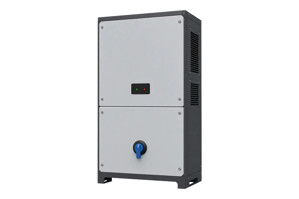
The INGECON SUN STORAGE 100TL is a 100 kW three-phase transformerless battery inverter for commercial and industrial storage, with Ethernet and Wi-Fi as standard and CAN Bus 2.0 to the battery BMS. Ingeteam publishes its input-register map: 37 documented points read with FC04, from inverter status, grid voltages, currents, frequency and power to DC power, battery temperature, alarms and state of charge. Edge reads them over Modbus TCP on port 502.
Compatibility
Compatible with EpiSensor Edge over Modbus TCP
Ingeteam's 100TL input-register document ABS2015IMB03 defines the online data as input registers read with function 0x04, numbered from 30001 at memory position 0. The installation manual names Modbus TCP on port 502 with the inverter on node 1. Edge is a Modbus TCP client and reads those registers directly from the inverter.
INGECON SUN STORAGE 100TL under input-register document ABS2015IMB03 revision B and installation manual ABS2014IQM01 revision A. Site check: read Battery SOC and Output active power once each and compare them with the inverter web application before adding further points. Modbus RTU needs Ingeteam's optional AAX7051 RS-485 kit. Read-only monitoring; EMS Gateway setpoints, charge and discharge commands are out of scope.
Connect it with


On every 100TL, through its standard Ethernet port on the site network
- Modbus
- Edge
- Platforms
When the inverter was fitted with Ingeteam's optional AAX7051 RS-485 communications kit and a wired network is not available
- Modbus
- Wireless
- Edge
- Platforms
When the site already runs the inverter's built-in INGECON SUN EMS and its EMS Gateway function has been enabled by the installer
- Wired
- Edge
- Platforms
Models
| Models | Interface | Route into Edge |
|---|---|---|
| INGECON SUN STORAGE 100TL | Three-phase transformerless battery inverter: Ethernet TCP and Wi-Fi as standard, CAN Bus 2.0 to the BMS, optional AAX7051 RS-485 kit | Modbus TCP on port 502, node 1, FC04 input registers from document ABS2015IMB03. |
| INGECON SUN STORAGE 350TL and the M Series and C Series HV PCS | Separate Ingeteam storage converters with their own datasheets | Do not apply the 100TL register map; obtain the matching Ingeteam communication document. |
| INGECON SUN STORAGE 1Play TL M | Single-phase hybrid inverter with its own input-register map | Use the separate 1Play TL M guide. |
Specifications
The 100TL is a bidirectional three-phase battery inverter rated at 100 kW discharging and 60 kW charging, for lithium-ion or lead batteries between 627 and 850 V DC. It carries an energy management system as standard, which runs self-consumption and can read an additional wattmeter for a non-Ingeteam PV system.2
- Power
- 100 kW discharge, 60 kW charge at the AC output; 145 A discharge and 87 A charge maximum current; 400 V rated, 50 / 60 Hz2
- Battery input
- 627 to 850 V DC operating range, 1,100 V maximum; 159 A discharge and 96 A charge maximum current; lithium-ion or lead2
- Efficiency
- 98.8% maximum, 98.1% Euroefficiency2
- Communication
- Ethernet TCP and Wi-Fi as standard; CAN Bus 2.0 to the BMS; RS-485 with the optional AAX7051 kit; EMS gateway over Modbus TCP23
- Modbus read
- FC04 Read Input Registers; register 30001 is memory position 0; node 1 on Modbus TCP port 50213
- Paralleling
- AC paralleling up to 12 battery units and 63 PV units2
- Environment
- IP65 / NEMA 4; -25 to 60 °C ambient, rated power to 50 °C; 0 to 100% relative humidity, non-condensing; 3,000 m maximum altitude; 80 kg2
Interface
Documented measurements and integration boundaries for SUN STORAGE 100TL.
- Inverter Status at 30021 (wire address 20), UINT16: 0 not ready to connect, 1 waiting to connect, 2 connected to the grid.
- Inverter Instantaneous Alarms 1 to 4 at 30015 to 30018 (wire 14 to 17), Stop Event at 30019 (wire 18) and Warning Code at 30020 (wire 19), all UINT16. Ingeteam's general definitions document AAA0030IMB07 decodes them; the 100TL map adds its own stop events 239 and 246 to 253.
- Output grid RMS current of phases 1, 2 and 3 at 30022 to 30024 (wire 21 to 23), UINT16 in A x 100: raw 14275 is 142.75 A.
- Grid RMS voltage of phases 1, 2 and 3 at 30025 to 30027 (wire 24 to 26), UINT16 in V x 10: raw 2300 is 230.0 V.
- Grid frequency at 30028 (wire 27), UINT16 in Hz x 100: raw 5000 is 50.00 Hz.
- Output apparent power at 30029 (wire 28), UINT16 in units of 10 VA; output active power at 30030 (wire 29) and output reactive power at 30031 (wire 30), INT16 in units of 10 W and 10 VAr. Multiply the raw value by 10. The map does not state which direction is positive, so set the sign from a known charge and a known discharge.
- Cosine of phi at 30032 (wire 31), INT16 x 1000.
- DC current at 30033 (wire 32), INT16 in A x 100; DC voltage at 30034 (wire 33), UINT16 in V; DC power at 30035 (wire 34), INT16 in units of 10 W.
- Isolation resistance at 30036 (wire 35), UINT16 in kOhm.
- Active power reduction rate at 30053 (wire 52), UINT16 in %, with its reason code at 30054 (wire 53), for example 11 self-consumption mode or 17 battery limit.
- Battery temperature at 30070 (wire 69), INT16 in °C; battery alarm bits at 30073 (wire 72), battery flag bits at 30074 (wire 73) and BMS communication status at 30075 (wire 74).
- Battery SOC at 31015 (wire 1014), UINT16 in %, and Battery FSM state at 31025 (wire 1024): 0 stand-by, 1 discharging, 2 constant-current charging, 3 constant-voltage charging, 4 floating, 5 equalising, 6 BMS communication error, 7 not configured.
- The map publishes no energy counters. Take charge and discharge energy from an EpiSensor ZEM on the inverter's AC feeder or from the site meter.
- Registers 30007 to 30014, 30037 to 30052, 30056 to 30069, 30071 and 30072, 30076 to 31014 and 31016 to 31024 are reserved for Ingeteam. Do not poll them.
Assessment
INGECON SUN STORAGE 100TL, read-only Modbus TCP under input-register document ABS2015IMB03 revision B, with the EMS Gateway input registers as an optional plant view.
- InteroperabilitySupported with conditions
- Ingeteam publishes the input-register map, the function code, the 30001 offset and the Modbus TCP port and node. Alarm and stop-event code definitions sit in a separate general document, and RS-485 needs an optional kit.13
- AccuracyLimited
- Per-phase voltage and current, frequency, P, Q, S, DC values, battery temperature and SOC have explicit scales. The map has no energy counters and does not state the sign convention of active power or DC current, and the datasheet states no measurement accuracy.12
- SecurityLimited
- The local Modbus TCP port has no documented authentication, and the EMS Gateway accepts setpoint writes. The inverter's own Wi-Fi access point is open from the factory and the manual recommends setting a password on it. Place the inverter on a segregated network.34
- ReliabilitySupported with conditions
- The datasheet lists the EMC, safety and environmental tests the inverter is built to and its protections. The EMS Gateway closes an idle connection after one hour and falls back to its default strategy with no client, so Edge must reconnect and treat a failed poll as stale.24
- RuggednessWell supported
- IP65 / NEMA 4, -25 to 60 °C with a stated derating rate, 0 to 100% humidity and 3,000 m altitude with a stated temperature derating above 1,000 m.2
Setup
Read Battery SOC, then the AC power block
Document ABS2015IMB03 revision B numbers input registers from 30001, which is memory position 0, and reads them with function 0x04. Battery SOC is register 31015 in %, and the grid block from 30028 holds frequency, apparent, active and reactive power and cosine of phi. The bytes below are computed from that map as a synthetic decoder check, not captured from an inverter.
- Target
- Inverter IP address, TCP port 502, unit identifier 1
- Address convention
- Wire address = register number minus 30001: register 31015 is address 1014 (0x03F6) and register 30028 is address 27 (0x001B). Sending 31015 or 1015 reads the wrong register.
- SOC request PDU
- 04 03 F6 00 01: FC04, address 0x03F6, one register. The TCP client adds the MBAP header.
- SOC response PDU
- 04 02 00 4B: one UINT16 of 0x004B = 75, so 75%.
- Power block request PDU
- 04 00 1B 00 05: FC04, address 0x001B (register 30028), five registers up to 30032.
- Power block response PDU
- 04 0A 13 88 26 7A 26 66 02 73 03 E6: frequency 0x1388 = 5000, so 50.00 Hz; apparent power 0x267A = 9850, so 98,500 VA; active power 0x2666 = 9830, so 98,300 W; reactive power 0x0273 = 627, so 6,270 VAr; cosine of phi 0x03E6 = 998, so 0.998.
- Consistency
- The square root of 98,300 squared plus 6,270 squared is 98,500 VA, and 98,300 / 98,500 is 0.998, so the decoded block agrees with itself.
- RS-485 equivalent
- With the AAX7051 kit, node 1: request 01 04 03 F6 00 01 D1 BC and response 01 04 02 00 4B F9 07, RTU CRC low byte first.
Acceptance: Keep the points when SOC matches the web application and active power matches it within the display resolution. Then record the sign under a known charge. These bytes are a synthetic decoder check, not a reply from a physical inverter.
-
Identify the inverter and its role
Record the nameplate, the inverter firmware and the battery make and model against Ingeteam's approved-battery list, which gives a minimum firmware for each battery. Note whether this unit is the EMS master inverter and whether an external controller already uses the EMS Gateway.
-
Put the inverter on a protected network
Connect the Ethernet TCP cable through an M20 gland to the RJ45 inside the wiring area. The inverter uses DHCP by default; set a fixed address in the web application or reserve one on the DHCP server. Keep port 502 reachable only from monitoring hosts.
-
Read status and state of charge first
Create a read-only Modbus TCP connection to port 502 with unit identifier 1. Read Inverter Status at 30021 (wire address 20) and Battery SOC at 31015 (wire address 1014) with FC04. Subtract 30001 from every register number to get the address on the wire.
-
Add AC, DC and battery points
Read the grid block from 30022 to 30036 and the battery registers at 30070, 30073 to 30075 and 31025. Apply the scales from the map: A x 100, V x 10, Hz x 100, and 10 VA, 10 W or 10 VAr per count for apparent, active and reactive power. Skip the reserved ranges.
-
Fix the power sign on site
The map gives active power and DC current as signed values without a direction. Read them during an existing charge and an existing discharge, compare with the web application, and record which sign is charging. Do not start a charge or discharge for the test.
Common questions
- Which function code reads the 100TL?
- Function 0x04, Read Input Registers. Ingeteam's document lists all online data as input registers from 30001, and register 30001 is memory position 0 on the wire.1
- Does the 100TL have RS-485 for Modbus RTU?
- Not as standard. The installation manual says RS-485 needs the AAX7051 communications kit, which supports every function except firmware loading. Ethernet TCP and Wi-Fi are standard.23
- Why does my active power look ten times too small?
- Output active power at 30030 is an INT16 in units of 10 W, so raw 9830 is 98,300 W. Apparent and reactive power and DC power use the same factor of 10.1
- Can Edge read charge and discharge energy from the 100TL?
- Not from this map: it has power, state of charge and status registers but no energy counters. Use an EpiSensor ZEM on the inverter's AC feeder or the site meter for kWh.1
- What is the EMS Gateway on port 522?
- A Modbus TCP server in the INGECON SUN EMS for external control of the whole plant, on port 522 with Modbus ID 01. Its input registers carry plant grid, PV and battery power and state of charge; its holding registers set the control mode and setpoints. Edge reads only the input registers.4
Related devices
More from Ingeteam
Sources
- INGECON SUN STORAGE 100TL input registers, ABS2015IMB03 revision B (opens in a new tab) (PDF)
- INGECON SUN STORAGE 100TL datasheet, ABS2020IQE01 (opens in a new tab) (PDF)
- INGECON SUN STORAGE 100TL installation and operation manual, ABS2014IQM01 revision A (opens in a new tab) (PDF)
- INGECON SUN EMS Gateway functionality specifications, AAX1068IMB01 revision J (opens in a new tab) (PDF)
- INGECON SUN STORAGE 100TL list of approved lithium-ion batteries, ABS2015IMB04 revision D (opens in a new tab) (PDF)
- INGECON SUN STORAGE 100TL product page (opens in a new tab)
Further reading
- ApplicationBattery storage performance monitoring
- ApplicationBattery demand response
- GuideBESS, BMS, EMS and PCS roles
- GuideModbus TCP and RTU integration
- ToolModbus register address converter
- ToolModbus data decoder
- ToolRS-485 termination and bias
- GuideModbus RS-485 commissioning
- ProtocolModbus devices and register maps
- CategoryInverters and charge controllers
- CategoryBattery systems and controls
Product names and trademarks belong to their owners. Publication does not imply endorsement or a commercial relationship.