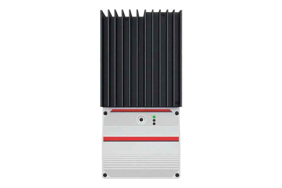
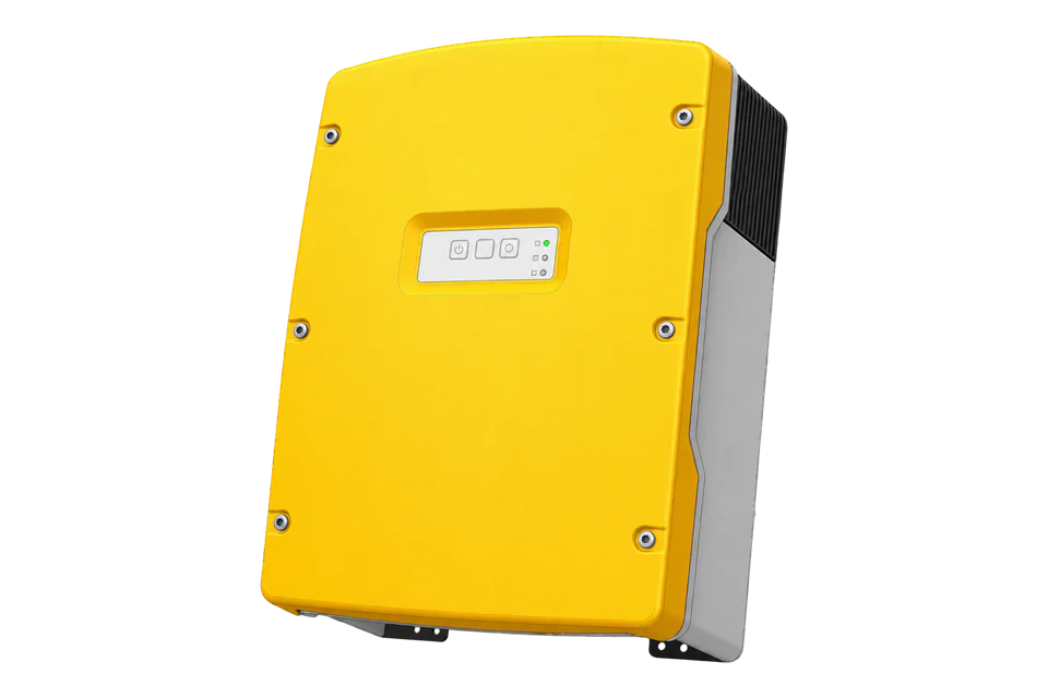
Morningstar TriStar MPPT 60
Solar battery charge controller
The 150V TriStar MPPT 60 combines solar battery charging with a built-in Ethernet interface. Its Modbus measurements use fixed-point scaling constants read from the controller, not one universal volts-per-count multiplier. This makes an initial scaling read as important as the battery-voltage address itself.
- Modbus TCP
Solar battery charge controller
Compatibility
Documented local Modbus TCP interface
Morningstar publishes a local Modbus TCP map with voltage/current scaling, battery and array measurements, charging state and fault points. The examples below provide a best-effort starting configuration for an Edge Modbus client; they are manufacturer-documented reads, not a physical-site validation.
TS-MPPT-60, 150V family, using MS-002582 Modbus specification v11. Not the TriStar PWM controller or TriStar MPPT 600V. The 30A and 45A versions do not inherit the 60A Ethernet interface. Read-only monitoring; charging setpoints remain under the established battery commissioning process.
Connect it with
-
Gateway ZGW-20From €899 ex VAT Configure Gateway
-
Evaluation Gateway on a Raspberry Pi Edge with one device licensedFree Set up Evaluation Gateway on a Raspberry Pi

For the TS-MPPT-60 local Ethernet interface
- Modbus
- Edge
- Platforms
Models
| Models | Interface | Route into Edge |
|---|---|---|
| TS-MPPT-60, 150V | Built-in Ethernet plus serial interfaces | Use the 150V TriStar MPPT map and read its scaling constants. |
| TS-MPPT-30 / TS-MPPT-45 | Different current ratings and communication-port availability | Do not assume the 60A model’s Ethernet path. |
| TriStar MPPT 600V and TriStar PWM | Different controller families and protocol definitions | Obtain their own register specifications rather than copying this point map. |
Specifications
- Map
- MS-002582 v11; addresses explicitly identify request PDU offsets1
- Ethernet defaults
- DHCP, TCP 502, Modbus ID 11
- Voltage scaling
- V_PU = whole + fraction / 65536; measurement = signed raw × V_PU / 327681
- Serial defaults
- 9600 baud, no parity, 8 data bits; the controller sends 2 stop bits and accepts 1 or 21
- Read functions
- FC03 holding or FC04 input-register reads as documented1
- Installation envelope
- IP20 / Type 1 indoor vented enclosure and -40 to +45 °C ambient range are documented; the housing is not an outdoor weatherproof enclosure.3
Interface
Documented measurements and integration boundaries for TriStar MPPT 60.
- V_PU at PDU addresses 0 and 1: whole and fractional parts of the voltage scaling constant.
- I_PU at addresses 2 and 3: the corresponding current scaling constant.
- Battery voltage at 0x0018 and battery terminal/sense measurements at 0x0019/0x001A.
- Array voltage and current, battery charging current and charge state from the named RAM variables.
- Controller faults and alarms alongside energy and daily-log quantities.
- Remote temperature-sensor disconnection has a specific sentinel; it must not appear as a real temperature.
Assessment
TS-MPPT-60 150V Ethernet monitoring using MS-002582 v11.
- InteroperabilityWell supported
- The public protocol defines functions, PDU addresses and fixed-point scaling with a complete voltage example.1
- AccuracySupported with conditions
- Voltage/current scalers and distinct terminal/sense points are documented. The hourmeter word-order inconsistency requires separate verification.1
- SecuritySupported with conditions
- The local interface includes writable charging and network parameters. The cited protocol does not establish encrypted or authenticated Modbus transport.1
- ReliabilitySupported with conditions
- Documented TCP socket behavior and status/fault points allow deliberate reconnect and stale-data handling.1
- RuggednessSupported with conditions
- IP20 / Type 1 indoor vented enclosure and -40 to +45 °C ambient range are documented; the housing is not an outdoor weatherproof enclosure.3
- ScalabilitySupported with conditions
- The networking guide covers routed/bridged arrangements, but the endpoint and unit ID must identify the intended controller rather than assume every model has Ethernet.12
- LifecycleSupported with conditions
- The protocol carries a version and date; retain it with controller firmware and revalidate scaling after equipment changes.1
Setup
Read battery voltage, charging current and power
Keep the manufacturer’s voltage example, then extend the same map with current and power. The added current/power payloads are synthetic decoder fixtures, not measurements from a connected controller.
- Scaling request
- FC03, address 0, length 2; PDU 03 00 00 00 02
- Scaling data
- 00 7B E0 41: V_PU = 123 + 57409/65536 = 123.87599182128906
- Voltage request
- FC03, PDU address 24, length 1; 03 00 18 00 01
- Voltage data
- 0D B0 = signed 16-bit 3504
- Decode
- 3504 × 123.87599182128906 / 32768 = 13.246504984796047 V
- Display comparison
- Approximately 13.25 V after rounding; compare the corresponding local measurement
- Current scaling
- FC03 at PDU address 2, length 2; request 03 00 02 00 02. I_PU = unsigned whole + unsigned fraction/65536. Synthetic data 00 40 00 00 gives I_PU = 64 A. Read the installed value rather than fixing it at 64.
- Battery and array current
- Battery current is signed S16 at PDU 28 (0x001C); array current is S16 at 29 (0x001D). FC03 request 03 00 1C 00 02 reads both. Each value is signed raw × I_PU/32768. Synthetic battery data 14 00 = 5120 gives 10.00 A with I_PU = 64. Register 39 (0x0027) is the separately filtered one-minute charging current.
- Output and input power
- FC03 at PDU 58 (0x003A), length 2; request 03 00 3A 00 02 reads output power then input power. Each is one unsigned U16: watts = raw × V_PU × I_PU/131072, not the voltage/current denominator 32768. Synthetic output 10 00 = 4096 gives about 247.752 W using V_PU = 123.87599182128906 and I_PU = 64. These are controller DC powers, not site AC import/export. The OEM notes that array input power can have significant error; use it for controller trends rather than billing.
- Charging state and quality
- Add charge_state at PDU 50 (0x0032), faults at 44 (0x002C), and alarm high/low words at 46/47 (0x002E/0x002F). Decode state/bitfields from the v11 tables, not as watts or amps. Compare battery current and output power with the same controller timestamp; their different filtering can prevent exact instantaneous equality. States: 4 fault, 5 MPPT, 6 absorption, 7 float, 8 equalize and 9 slave.
Acceptance: This example verifies the fixed-point method, not a permanent device-wide multiplier. Read the scaling constants from the actual controller; replacing them with the example values can produce plausible but incorrect readings.
-
Identify the 150V controller
Record TS-MPPT-60 from the nameplate and note firmware. The 600V product and PWM TriStar use different maps. Verify that the chosen network endpoint is the controller rather than an unrelated bridge.
-
Establish the protected Ethernet connection
Find its DHCP lease or documented network configuration. Use the configured unit ID and TCP port, normally 1 and 502. Keep the local monitoring interface off the public internet; network reachability does not make write commands safe.
-
Read scaling before measurements
Read holding registers 0 and 1 together for V_PU, then 2 and 3 for I_PU. Decode each whole-plus-fraction constant using denominator 65536. Retain those values with the device configuration and refresh them after replacement or firmware changes.
-
Verify one battery-voltage point
Read one register at PDU address 24 (0x0018). Decode its signed 16-bit raw value and multiply by V_PU/32768. Compare with the controller display or an appropriate reference at the same electrical boundary.
-
Make polling resilient
After voltage, read battery/array current at PDU 28/29 using I_PU/32768, then output/input power at 58/59 using V_PU × I_PU/131072. Add charging state 50, faults 44 and alarms 46/47. Keep reserved gaps out of blocks, handle reconnects where the controller closes TCP after a reply, and leave charging settings unchanged.
Related devices
Sources
- TriStar MPPT Modbus specification MS-002582 v11, 21 August 2018 (opens in a new tab) (PDF)
- TriStar MPPT networking companion document (opens in a new tab) (PDF)
- TriStar MPPT 150V operator’s manual (opens in a new tab) (PDF)
Further reading
Product names and trademarks belong to their owners. Publication does not imply endorsement or a commercial relationship.