KOSTAL Solar Electric PIKO CI 30/50/60
Commercial PV inverter
KOSTAL PIKO CI 30, 50 and 60 inverters connect to EpiSensor Edge over Modbus TCP on TCP port 1502 with unit ID 71, or over Modbus RTU on the COM2 RS485 terminals. KOSTAL's interface description revision 1.5 gives the KOSTAL register table and the SunSpec models 1, 103, 113, 120, 123 and 160. Read the AC phase count first, then generation power with its scale factor, and compare with the inverter app.
Compatibility
Compatible with EpiSensor Edge over Modbus TCP or Modbus RTU
KOSTAL's PIKO CI interface description revision 1.5 documents Modbus TCP (port 1502, unit ID 71), RS485 Modbus RTU, FC03 reads and a register table with formats and units, plus SunSpec model start addresses. Edge reads them as a Modbus TCP client on the site network, or as a Modbus RTU client through a ZMB-31 Modbus Interface or the Gateway serial port.
PIKO CI 30, 50 and 60 with firmware V3.17, from interface description revision 1.5 (11 August 2025) and the PIKO CI 30/50/60 operating manual (CB 012801 or 012601, CSB 013001). The same interface description covers PIKO CI 30/50 G2 and PIKO CI 100, whose wiring is in their own manuals. Site check: read the AC phase count and generation power, then compare with the KOSTAL PIKO CI app.
Connect it with


When the inverter's LAN port is on the site network
- Modbus
- Edge
- Platforms
When RS485 is not used by an energy meter, park controller or another data logger
- Modbus
- Wireless
- Edge
- Platforms
Models
| Models | Interface | Route into Edge |
|---|---|---|
| PIKO CI 30 | 30 kW, two MPPTs, six DC inputs, 2x LAN, Wi-Fi, RS485 | Read DC1 and DC2 values; DC3 and DC4 registers apply only where MPPTs exist. |
| PIKO CI 50 / PIKO CI 60 | 50 or 60 kW, four MPPTs, 10 or 12 DC inputs, 2x LAN, Wi-Fi, RS485 | Read DC1 to DC4; SunSpec model 160 at 40239 carries four MPPT modules. |
| PIKO CI 30/50 G2 and PIKO CI 100 | Same interface description, TCP port 1502 and unit ID 71 | Use the register table here; take wiring and error-bit support from that model's own manual and the table's model columns. |
Specifications
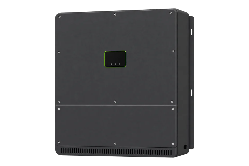
The PIKO CI is a transformerless three-phase string inverter for medium and large PV systems, for TT, TN-C, TN-S and TN-C-S grids. The COM2 panel carries two LAN sockets, the RS485 terminals and four digital inputs; Wi-Fi is built in. Modbus data updates once a second.2
- Rated power
- 30, 50 or 60 kW (cos φ = 1)2
- Independent MPP trackers
- 2 (PIKO CI 30); 4 (PIKO CI 50 and 60)2
- Interfaces
- 2x Ethernet LAN (RJ45), Wi-Fi 2.4 GHz, 1x RS485, 4 digital inputs2
- Modbus TCP defaults
- TCP port 1502, unit ID 71 (modifiable)1
- RS485 settings in the interface description
- RTU, half duplex, 19200 baud, 8 data bits, no parity, 2 stop bits1
- SunSpec models
- 1, 103, 113, 120, 123, 160 and end model, starting at 40003 in KOSTAL's numbering1
- Protection class
- IP 652
- Ambient temperature
- -25 to 60 °C; up to 4000 m2
Interface
Documented measurements and integration boundaries for PIKO CI 30/50/60.
- Send the hex address in the KOSTAL table as the PDU start address with FC03 (for example 0x00AC for total AC active power). Reads may span 1 to 125 registers.
- Identity: 0x0006 article number and 0x000E serial number (strings, 8 registers), 0x0020 number of AC phases (U16), 0x0022 number of PV strings (U16), 0x0038 inverter state (1 init, 6 feed-in, 10 standby, 15 shutdown), 0x0300 product name and 0x0320 power class (strings).
- Integer AC values with scale factors: 0x023F inverter generation power (S16, W) with power scale factor at 0x0240; 0x0241 generation energy (U32, Wh) with energy scale factor at 0x0243. Scale factors are signed 16-bit, range -10 to 10.
- Float AC values (R32, two registers): 0x0098 grid frequency (Hz), 0x009A to 0x00AA phase 1 to 3 current, active power and voltage, 0x00AC total AC active power (W), 0x00AE reactive power (var), 0x00B2 apparent power (VA), 0x0140 total yield (Wh).
- Float DC values: 0x0064 total DC power, 0x0102 to 0x010A DC1 current, power and voltage, then DC2 at 0x010C, DC3 at 0x0116 and DC4 at 0x012C. The interface description gives a 16-bit big-endian example and no R32 example, so the register order of a float is fixed on site.
- Powermeter values from 0x00DA to 0x00FC belong to a connected energy meter, not to the inverter. The sign of 0x00FC depends on sensor position: home consumption or grid connection.
- Error bit fields: 0x101E, 0x101F and 0x1020 (U16), for example bit 2 of 0x101F is grid absent. The interface description marks which bits each PIKO CI model supports.
Assessment
PIKO CI 30, 50 and 60, firmware V3.17, from interface description revision 1.5 and the PIKO CI 30/50/60 operating manual. Confirm the phase count read and compare generation power with the KOSTAL app.
- InteroperabilitySupported with conditions
- The interface description gives port, unit ID, function codes, formats and SunSpec model addresses; the R32 register order has no documented example and is fixed on site.13
- AccuracySupported with conditions
- AC, DC and energy values carry units, and the integer generation registers carry explicit scale factors. Meter registers must stay separate from inverter values.1
- SecurityLimited
- KOSTAL warns that an exposed Modbus interface allows manipulation, advises a firewall, VPN and no port forwarding, and the register table includes the app login password at 0x3158 as read-write.1
- ReliabilityNot yet assessed
- Modbus data updates once a second, but no polling limit, timeout or recovery behaviour is published for TCP clients.12
- RuggednessWell supported
- IP 65, -25 to 60 °C, 0 to 100 % humidity and operation up to 4000 m, for indoor and outdoor installation.2
- ScalabilitySupported with conditions
- Each inverter has its own IP endpoint and modifiable unit ID; on RS485 one host can address up to 247 inverters.12
- LifecycleSupported with conditions
- The interface description carries a revision, release date and firmware validity per model; recheck the phase count and power reads after a firmware update.1
Setup
Check the address offset, then decode generation power
Modbus TCP on port 1502 with unit ID 71 (0x47). The ADUs below are the MBAP header followed by the PDU. These are synthetic decoder checks, not captured inverter responses.
- Phase count request
- 00 01 00 00 00 06 47 03 00 20 00 01: transaction 1, length 6, unit 71, FC03 at 0x0020, quantity 1.
- Phase count reply
- 00 01 00 00 00 05 47 03 02 00 03: one register, value 3, so the address convention and unit ID are right.
- Power request
- 00 02 00 00 00 06 47 03 02 3F 00 02: FC03 at 0x023F, quantity 2, generation power and its scale factor.
- Synthetic power reply
- 00 02 00 00 00 07 47 03 04 0B B8 00 01: power 0x0BB8 = 3000 and scale factor 0x0001 = +1, so 3000 × 10^1 = 30000 W.
- SunSpec numbering
- KOSTAL starts the Common model at 40003 and model 103 at 40071. The SunSpec specification puts the SunS marker at 0-based address 40000, so a 0-based client reads the Common model ID at 40002; read the marker first to fix the offset.
Acceptance: Accept the read when 0x0020 returns 3 and generation power agrees with the KOSTAL app within normal sampling differences. A scale factor outside -10 to 10 or an exception reply means the request reached the wrong register.
-
Use the matching document
This guide uses KOSTAL's PIKO CI interface description revision 1.5 (firmware V3.17 for PIKO CI 30/50/60) and the PIKO CI 30/50/60 operating manual. Record the CB and CSB versions from the app; the CSB version is also readable at 0x1A60.
-
Connect on TCP port 1502
Connect the inverter's LAN socket to the site network and set Edge to TCP port 1502, unit ID 71. The interface description lists a MODBUS Enable flag at 0x0002 and the unit ID at 0x0004; if there is no reply, check those settings with the installer rather than writing them from Edge.
-
Read a known integer first
Read FC03 at 0x0020, quantity 1. A PIKO CI is three-phase, so the reply must be 3. A different value means the address offset, unit ID or device is wrong; resolve that before mapping more points.
-
Read generation power with its scale factor
Read 0x023F, quantity 2: the first word is generation power (S16, W) and the second the power scale factor (S16). Power is value × 10^scale factor. Compare it with the KOSTAL PIKO CI app while the inverter state at 0x0038 is 6 (feed-in).
-
Settle the float word order before adding R32 points
The interface description shows big-endian encoding with a 16-bit example only and no example for R32 values. Read total AC active power at 0x00AC as two registers, decode it both ways, and keep the order that agrees with the scaled integer from 0x023F. Then add frequency, phase and DC points in the same order.
Common questions
- Which word order do the PIKO CI float registers use?
- The interface description shows big-endian encoding with a 16-bit example and gives no R32 example, so the order of the two registers in a float is not documented. Fix it on site by comparing 0x00AC with the scaled integer generation power at 0x023F.1
- Are the powermeter registers the inverter's output?
- No. Registers 0x00DA to 0x00FC carry the values of a connected energy meter. Their sign depends on whether the sensor is set to home consumption or the grid connection, so keep them separate from the inverter's AC values.1
Related devices
Sources
- PIKO CI interface description KOSTAL MODBUS (TCP) with control information, revision 1.5, 11 August 2025 (opens in a new tab) (PDF)
- PIKO CI solar inverter 30/50/60 kW operating manual, English, 2025 (opens in a new tab) (PDF)
- SunSpec Device Information Model Specification 1.1 (opens in a new tab) (PDF)
Further reading
Product names and trademarks belong to their owners. Publication does not imply endorsement or a commercial relationship.