Continental Control Systems WattNode WND-WR-MB
CT-connected energy meter
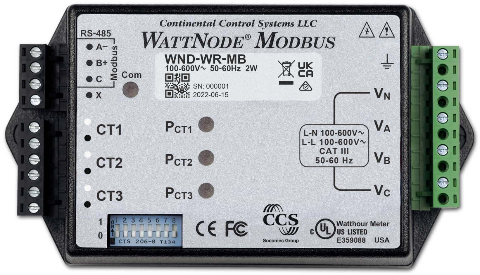
The WattNode Wide-Range for Modbus, model WND-WR-MB, is Continental Control Systems' fourth-generation (WND series) WattNode meter. One model covers any single-phase, split-phase or three-phase service from 100 to 600 Vac, wye or delta, and the meter powers itself from its VA and VB voltage terminals. It has no display and no current terminals for the load: current comes from up to three external CTs with a 0.333 Vac output at rated current, and each CT forms a meter element with a voltage channel that can be reassigned in registers. It reports active, reactive and apparent power and energy per element and in total, voltage, current, power factor, frequency and demand on a half-duplex RS-485 port running Modbus RTU. CCS documents the registers one-based, so the address on the wire is one less, and its 32-bit registers send the least significant word first. The same map also carries SunSpec models 1, 203 and 213, which are big-endian.
Compatibility
Compatible with EpiSensor Edge over Modbus RTU
The WND-WR-MB is compatible with EpiSensor Edge over Modbus RTU on its RS-485 terminals, read through a ZMB-31 Modbus Interface or a Gateway serial port. Continental Control Systems publishes the complete register list with the one-based address convention, function codes 03 and 04, data types, units, scaling and the 32-bit word order.
WattNode Wide-Range for Modbus WND-WR-MB, firmware 1033 and later and hardware version 8 and later, using reference manual WND-WR-MB-Ref-1.02. Earlier WNC-series WattNode Modbus meters are not covered. Site check: read the float VoltAN at 1019 and 1020, low word first, and the integer VoltAN at 1214, and compare both with a handheld meter on the VA to VN terminals. Read-only monitoring: no writes to the CT, metering, passcode, energy reset or communication registers.
Connect it with
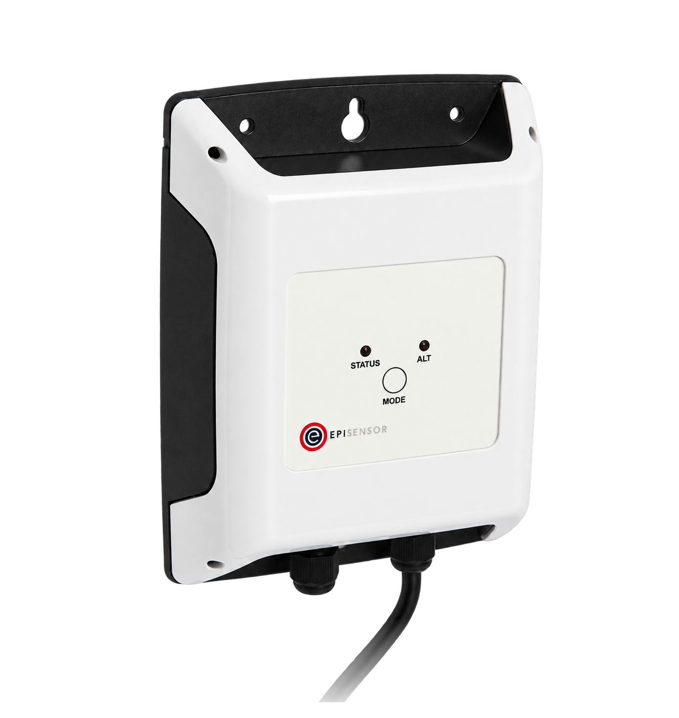
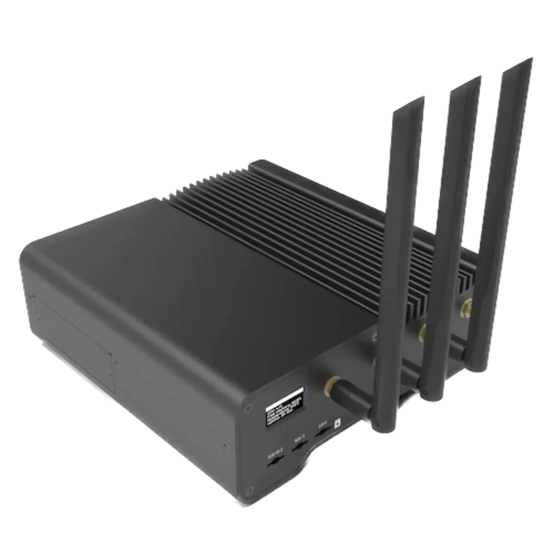
For a WattNode in a panel or meter enclosure where a wireless link avoids running a data cable back to the Gateway
- Modbus
- Wireless
- Edge
- Platforms
When the Gateway sits near the meters, or several WattNode meters share one wired RS-485 bus
- Modbus
- Edge
- Platforms
Models
| Models | Interface | Route into Edge |
|---|---|---|
| WattNode Wide-Range for Modbus · WND-WR-MB | Three 0.333 Vac CT inputs; VN, VA, VB and VC voltage inputs, 100 to 600 Vac, with the meter powered from VA and VB; half-duplex RS-485 Modbus RTU on A-, B+ and C; eight-position DIP switch for address, termination and baud rate | Read the CCS float or integer registers with FC03 or FC04 on either serial path. Model register 1707 reads 510 for every WattNode Wide-Range Modbus meter. |
| WND-WR-MB with factory options (CT=, AD=, baud rate, EP, 8N2, L, MA, T1) | Same meter and register map. AD= and the baud-rate options replace the DIP switch address or baud rate; EP sets 8E1 and 8N2 two stop bits; L locks the CT and metering configuration; MA and R are for milliamp-output CTs; T1 fits a fixed terminator and bias resistors | Same read path. Take the address, baud rate and parity from the options printed on the front label, or read OptAddress, OptBaudRate and OptParityMode at 1728 to 1730. |
| WNC-series WattNode Modbus meters | The previous, third generation of WattNode Modbus meters, with a separate manual | Not covered by this guide. CCS states that a system set up for a WNC meter keeps working with a WND meter; the WND adds registers the WNC lacks, such as SunSpec, CT status and positive and negative reactive energy. Use the WNC manual for a WNC meter. |
Specifications
- Model
- One model, WND-WR-MB, for every service from 100 to 600 Vac; all units are revenue grade, and a certificate of calibration is a separate item, WN-CAL-CERT. The reference manual covers firmware 1033 and later and hardware version 8 and later.12
- Current inputs
- Three inputs for external CTs with a 0.33333 Vac output at rated current (input impedance 23 kΩ, absolute maximum 5.0 Vac); 40 mA output CTs only with factory option MA or R. CT rated current is set per input from 0 to 30000 A. 1 A and 5 A output CTs must not be connected: CCS warns that they destroy the meter.12
- Voltage inputs and supply
- VN, VA, VB and VC; 100 to 600 Vac nominal, line-to-neutral 90 to 347 Vac and line-to-line 120 to 600 Vac; 690 Vac maximum; 45 to 65 Hz; measurement category CAT III 600 V. The meter is powered from VA and VB, minimum 85 Vac. PT ratio 0.05 to 300 for potential transformers.1
- Accuracy
- Active energy ±0.5% maximum (±0.2% typical), active power, voltage and current ±0.5% maximum, excluding CT errors. Meets ANSI C12.1-2008 and ANSI C12.20-2010 class 0.5 without CT errors; as a system, ANSI C12.20 class 0.5 with class 0.2 or 0.3 CTs and ANSI C12.1 with class 0.6 CTs.1
- Modbus RTU
- Half-duplex RS-485, two wires plus common, isolated 4500 Vac RMS. Address 1 to 63 by DIP switch or 1 to 247 by register; 9600 or 19200 baud by DIP switch 8, 1200 to 115200 baud by register; 8N1 by default, 8E1 and 8N2 optional. FC03, FC04, FC06, FC16 and FC17. Typical response 5 to 25 ms; 256-byte buffer.12
- Bus loading and termination
- 1/8 unit load receiver, up to 256 WattNode meters on one subnet. DIP switch 7 switches an internal 120 Ω terminator; the meter has a failsafe receiver and no bias resistors (option T1 fits a fixed terminator and bias). Maximum bus length unterminated: 860 m (2822 ft) at 9600 baud, 430 m (1411 ft) at 19200, 215 m at 38400 and 70 m (230 ft) at 115200; terminated at both ends: 1220 m (4000 ft) up to 76800 baud and 990 m (3250 ft) at 115200.12
- Approvals
- UL Listed for the U.S. and Canada, file E359088, to UL/IEC 61010-1 3rd edition and CAN/CSA-C22.2 No. 61010-1-12; FCC Part 15 class B; CE to the Low Voltage and EMC directives, EN 61326-1:2013 industrial locations; RoHS.1
- Environment
- Operating -40 to +80 °C; 5 to 90% relative humidity up to 40 °C, non-condensing, falling to 50% at 55 °C; altitude up to 3000 m; pollution degree 2; IP40. Indoor use, or outdoors inside an enclosure rated NEMA 3R or 4.1
- Housing
- 153 × 85.1 × 38.0 mm, 233 g, ABS/PC rated UL 94V-0. Pluggable terminal blocks for up to 2.5 mm² (12 AWG); two mounting holes 137 mm apart under the terminal blocks.1
Interface
Documented measurements and integration boundaries for WattNode WND-WR-MB.
- CCS documents register numbers one-based and the wire address is one less: EnergySum is documented at 1001 and sent as 1000 (0x03E8). Modbus software that asks for register numbers takes 1001 as printed. The meter does not use the 3xxxx or 4xxxx prefixes, and FC03 and FC04 read any register.
- 32-bit floats and 32-bit integers occupy two registers and are little-endian: the first, lower-addressed register holds the least significant 16 bits. Clients call this float or long swapped; Tridium JACE calls it byte order 1032. Read both registers in one request so the value cannot change between them.
- Float voltages in V: VoltAvgLN 1017, VoltAN 1019, VoltBN 1021, VoltCN 1023, VoltAvgLL 1025, VoltAB 1027, VoltBC 1029 and VoltCA 1031, two registers each. Frequency Freq at 1033 in Hz. A voltage channel below 20% of the nominal voltage, or of the highest measured voltage if that is higher, is treated as inactive and reads zero.
- Float active power in W: PowerSum 1009 and Power1 to Power3 at 1011, 1013 and 1015, averaged over 5 seconds by default. PowerFastSum 1037 and PowerFast1 to PowerFast3 at 1039 to 1043 update every 100 ms with no averaging. Reactive power PowerReacSum 1147 (VAR) and apparent power PowerAppSum 1155 (VA), each followed by elements 1 to 3.
- Float current in A: Current1 to Current3 at 1163, 1165 and 1167, unsigned by default. Power factor PowerFactorAvg at 1139 and elements 1 to 3 at 1141 to 1145; it includes harmonics and is negative when the element's power is negative.
- Float energy in kWh: EnergySum 1001 (net), EnergyPosSum 1003, EnergySumNR 1005, EnergyPosSumNR 1007 and EnergyNegSum 1113, with per-element registers from 1101. Reactive energy EnergyReacSum 1123 (kVARh) and apparent energy EnergyAppSum 1131 (kVAh). Above 100,000 kWh a float's resolution becomes coarser than 0.1 kWh.
- Integer energy, 32-bit signed, low word first, in 0.1 kWh: EnergySum 1201, EnergyPosSum 1203, EnergySumNR 1205, EnergyPosSumNR 1207, EnergyNegSum 1313 and EnergyNegSumNR 1315; per element from 1301. CCS suggests these for energy because their resolution stays at 0.1 kWh. The NR (non-resettable) registers cannot be zeroed or preset.
- Negative energy registers report a positive number: 1000 kWh of exported energy reads 1000 in EnergyNegSum. Power is negative when the element generates or its CT is reversed.
- Integer measurements are single 16-bit signed registers: VoltAN to VoltCA at 1214 to 1220 and VoltAvgLN at 1213 in 0.1 V; Freq at 1221 in 0.1 Hz; power factor at 1339 to 1342 in 0.01.
- Integer power, reactive power, apparent power and demand (1209 to 1212, 1343 to 1350, 1354 to 1360) are multiplied by PowerIntScale at 1609, which reads the factor in use (1, 10, 100, 1000 or 10000) when set to automatic. CCS's example: PowerSum 2500 with PowerIntScale 100 is 250,000 W.
- Integer current at 1351 to 1353 is scaled amps: current = register × CtAmpsX / CurrentIntScale, with CtAmps1 to CtAmps3 at 1604 to 1606 and CurrentIntScale at 1622 (default 20000). CCS's example: 5000 with 200 A CTs is 50.00 A. The float current registers need no scaling.
- Demand in W: DemandSum 1169, DemandSumMin 1171, DemandSumMax 1173, DemandAppSum 1175 and Demand1 to Demand3 at 1177 to 1181, over a 15-minute period by default (DemPerMins at 1610). Demand reads zero until one full interval has passed after power-up.
- Identity and health: SerialNumber at 1701 (32-bit), Model at 1707 (510), firmware Version at 1708, ErrorStatus1 at 1716 (0 = no errors) and CtStatus1 to CtStatus3 at 1760 to 1762 when disconnected-CT detection is enabled. Dummy at 0001 always returns 0.
- SunSpec models 1, 203, 213 and 64080 start at 40001 one-based (40000 on the wire) and are big-endian, the opposite word order to the CCS registers. Use one register set per Edge configuration and keep its word order.
- Configuration and command registers from 1601 to 1659 (passcode, CT amps, CT directions, averaging, scaling, ZeroEnergy, ZeroDemand, meter element configuration, PT ratio, address, baud rate and parity) accept FC06 and FC16 writes. Never write them from a monitoring configuration.
Assessment
WattNode Wide-Range for Modbus WND-WR-MB, firmware 1033 and later and hardware version 8 and later, using reference manual WND-WR-MB-Ref-1.02. Earlier WNC-series WattNode Modbus meters are not covered. Site check: read the float VoltAN at 1019 and 1020, low word first, and the integer VoltAN at 1214, and compare both with a handheld meter on the VA to VN terminals. Read-only monitoring: no writes to the CT, metering, passcode, energy reset or communication registers.
- InteroperabilityWell supported
- CCS publishes the complete register list with the one-based address convention and its wire offset, FC03 and FC04 reading any register, float and integer data types, units, scaling equations and the low-word-first order of 32-bit values. The same map carries SunSpec models 1, 203 and 213, and the meter identifies itself to FC17.1
- AccuracySupported with conditions
- Per-element and total active, reactive and apparent power and energy, positive and negative energy, voltages, currents, power factor and demand, with ±0.5% maximum energy error and ANSI C12.20 class 0.5 excluding CTs. System accuracy depends on the CTs: class 0.2 or 0.3 CTs for ANSI C12.20 class 0.5, class 0.6 for ANSI C12.1. The approvals are ANSI and UL; the manual cites no MID or IEC metering class.12
- SecuritySupported with conditions
- A 32-bit ConfigPasscode can lock the configuration and energy and demand resets, with a five-second lockout after a wrong passcode; factory option L locks the CT and metering settings; the NR energy registers cannot be reset or preset. The passcode is disabled as shipped, and Modbus RTU itself has no authentication or encryption, so the RS-485 segment has to be physically controlled.1
- ReliabilitySupported with conditions
- Energy registers are written to ferroelectric memory every second and survive power loss; a power-fail count, uptime, eight error-status registers and disconnected-CT detection are readable over Modbus. The meter is line powered from VA and VB, minimum 85 Vac, so it stops counting when those terminals are dead. Type tested to UL/IEC 61010-1 and EN 61326-1 industrial immunity.1
- RuggednessSupported with conditions
- Operating -40 to +80 °C, up to 3000 m, CAT III 600 V voltage inputs and 4500 Vac RS-485 isolation. The case is IP40, so it needs a panel or an enclosure rated NEMA 3R or 4 outdoors, and the terminal screws are not insulated.1
- ScalabilitySupported with conditions
- 1/8 unit load allows up to 256 meters per subnet, with addresses 1 to 247 by register or 1 to 63 by DIP switch, baud rates to 115200 and a typical response of 5 to 25 ms. Unterminated, the maximum bus length falls as the baud rate rises: 860 m at 9600, 430 m at 19200, 215 m at 38400 and 70 m at 115200; terminated, it is 1220 m up to 76800 baud. DIP-switch addressing alone stops at 63 meters.12
- LifecycleSupported with conditions
- The reference manual was revised in July 2023 for hardware version 8, documents register changes from the WNC series and firmware-dependent behaviour, and CCS gives a five-year warranty. Firmware upgrades over Modbus need custom software from CCS, and the manual describes no configuration backup or restore.1
Setup
Read VoltAN from registers 1019 and 1020
CCS's WattNode Wide-Range for Modbus reference manual Rev 1.02 (WND-WR-MB-Ref-1.02) lists VoltAN, the RMS voltage from VA to VN, as a float at registers 1019 and 1020 in volts, and the same quantity as a 16-bit integer at 1214 in 0.1 V. It documents registers one-based and 32-bit values with the least significant register first. The meter has no display, so the check compares the float with the integer register and with a handheld meter.
- Request
- 01 03 03 FA 00 02 E4 7E: slave address 1 (set on the DIP switch), FC03, wire address 03FAh, two registers, RTU CRC with the low byte first. FC04 with the same address returns the same registers.
- Address convention
- Register 1019 is one-based; subtract one for the wire: 1018 decimal, 03FAh. A client that asks for register numbers takes 1019 as printed. Do not send 03FBh, which starts one register late and pairs 1020 with 1021.
- Synthetic response
- 01 03 04 99 9A 42 F0 C4 64: four data bytes, register 1019 = 999Ah first, then register 1020 = 42F0h.
- Decode
- Put the second register in the high half: 42F0 999Ah as an IEEE 754 float32 is 120.3, so VoltAN is 120.3 V with no scaling. A client that takes the first register as the high word decodes 999A 42F0h, about -1.6 × 10⁻²³: the sign of the wrong word order.
- Integer cross-check
- 01 03 04 BD 00 01 15 1E reads register 1214 (wire address 1213, 04BDh). A synthetic reply 01 03 02 04 B3 FB 31 holds 04B3h = 1203, which at 0.1 V is 120.3 V.
- Acceptance
- Keep the point when the float, the integer register and a handheld meter on VA to VN agree at the same time. If the float is far off and the integer is right, change the word order in the client before adding more points.
Acceptance: The response bytes are a synthetic decoder check, not a captured meter reply. A real reply must agree with the integer register and a handheld meter before current, power and energy points are enabled; each of those has its own unit and, in the integer set, its own scale.
-
Identify the meter and its options
Check that the label reads WND-WR-MB and note any options printed on it, such as EP, 8N2, AD= or a baud rate, which change the communication settings. Record the rated current of each CT and which voltage phase it sits on.
-
Read the DIP switch
DIP switches 1 to 6 set the address from 1 to 63 (values 1, 2, 4, 8, 16 and 32), switch 7 the internal terminator and switch 8 the baud rate: down for 9600, up for 19200. The meter ships set to address 0, which is invalid: the Com LED lights solid red and the meter does not answer.
-
Wire the RS-485 bus
Connect A-, B+ and the C common in a daisy chain, never home runs. Earth the shield or common at the Gateway end only. A bus longer than 860 m at 9600 baud or 430 m at 19200 needs 120 Ω at both ends, using DIP switch 7 on the last meter.
-
Make the first reads
Read Model at 1707, one register: it returns 510. Then read the float VoltAN at 1019 and 1020 low word first, as in the worked read below, and the integer VoltAN at 1214 in 0.1 V. Both should agree with each other and with a handheld meter on VA to VN.
-
Check the CT configuration
Read CtAmps1 to CtAmps3 at 1604 to 1606 and compare them with the CTs fitted; the factory value is 5. A wrong value scales every current, power and energy reading, and correcting it belongs to the meter's commissioning, not to Edge's read-only poll. Check that ErrorStatus1 at 1716 reads 0 and that Power1 to Power3 are positive on a consuming load.
-
Add the points you need
Add the float power, current and voltage registers, and the 32-bit integer energy registers in 0.1 kWh for counters that keep their resolution. Keep the configuration, reset and communication registers out of the polling configuration.
Common questions
- Is the WattNode address 1019 or 1018?
- Both, depending on where you type it. CCS documents registers one-based, so a Modbus tool that asks for register numbers takes 1019. On the wire the address is one less, 1018 (03FAh). CCS's own example: EnergySum at 1001 goes on the bus as 1000, 0x03E8.1
- Why are my WattNode float values huge, tiny or invalid?
- The CCS registers send the least significant 16 bits first. Set the client to the swapped or reversed float and long order (byte order 1032 on a Tridium JACE) and read both registers in one request. The SunSpec registers from 40001 are the other way round, most significant word first.1
- How do I convert the WattNode integer current to amps?
- Multiply by the CT rated current and divide by CurrentIntScale: current = Current1 × CtAmps1 / CurrentIntScale. With 200 A CTs and the default CurrentIntScale of 20000, a reading of 5000 is 50.00 A. The float current registers at 1163 to 1167 are already in amps.1
- Which energy register should I use for kWh?
- For energy drawn from the supply, EnergyPosSum: the float at 1003 in kWh or the 32-bit integer at 1203 in 0.1 kWh, low word first. CCS suggests the integer for energy, because a float's resolution becomes coarser than 0.1 kWh above 100,000 kWh. EnergySumNR and EnergyPosSumNR cannot be reset.1
- Can the WattNode be used with 5 A CTs?
- No. The WND-WR-MB takes CTs with a 0.333 Vac output at rated current, or 40 mA output CTs on a meter ordered with option MA or R. CCS warns that 1 A or 5 A output CTs, usually labelled with a ratio such as 100:5, destroy the meter.12
- Does the WattNode Modbus have Modbus TCP?
- No. The WND-WR-MB has an RS-485 port running Modbus RTU only. CCS notes that earlier WattNode Modbus firmware carried Modbus TCP framing over RS-485 and that this was removed. Edge reads it through a ZMB-31 or a Gateway serial port.1
- The WattNode does not answer and the Com LED is solid red. What is wrong?
- The DIP switch is at address 0, which is how the meter ships and which is invalid. Set switches 1 to 6 to a unique address from 1 to 63. A Com LED that flashes red for one second instead points to a CRC or framing error: check the baud rate, parity and the A- and B+ wiring.1
Related devices
Sources
- WattNode Wide-Range for Modbus electric power meter reference manual, model WND-WR-MB, document WND-WR-MB-Ref-1.02 (Rev 1.02, 6 July 2023; firmware 1033 and later, hardware version 8 and later) (opens in a new tab) (PDF)
- WND-WR-MB WattNode Wide-Range Modbus Meter datasheet, document WND-WR-MB-DS1 (2020-02-12) (opens in a new tab) (PDF)
Further reading
- ToolModbus register address translator
- ToolModbus data decoder
- ToolModbus CRC and LRC calculator
- GuideCT meters: how CT-operated electricity meters work
- GuideModbus register maps: addresses, data types and scaling
- GuideModbus commissioning over RS-485
- ProtocolModbus devices and register maps
- CategoryEnergy meters
Product names and trademarks belong to their owners. Publication does not imply endorsement or a commercial relationship.