Lovato DMG7000 to DMG9000
Power and energy meter
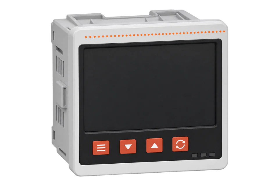
The DMG7000, DMG7500, DMG8000 and DMG9000 are Lovato's current power analysers for a 92 x 92 mm panel cut-out, with a widescreen colour display and three EXP expansion slots. The DMG7500 has a built-in isolated RS-485 port, the DMG8000 a built-in Ethernet port with a web server, and the DMG9000 both, plus a measured neutral and EN 50160 quality statistics. All of them answer Modbus RTU, ASCII or TCP from the register map in Lovato's Modbus manual I676IGB10_25, which sends 32-bit values high word first, gives power in kW/100000 and keeps the energy totals in four-register counters that Edge's Modbus client does not read.
Compatibility
Compatible with EpiSensor Edge over Modbus TCP or Modbus RTU
The DMG7500, DMG8000 and DMG9000 are compatible with EpiSensor Edge over Modbus RTU on the built-in RS-485 port (DMG7500, DMG9000), read through a ZMB-31 Modbus Interface or a Gateway serial port, and over Modbus TCP on port 502 of the built-in Ethernet port (DMG8000, DMG9000). Lovato publishes one register map with addresses, word counts, units and formats for read functions 03 and 04, and states big-endian word order.
DMG7000, DMG7500, DMG8000 and DMG9000, read with Modbus manual I676IGB10_25 and instruction manual I674IGB09_26. The DMG7000 has no built-in port and needs an EXP communication module; the DMG7501 speaks BACnet MS/TP only on its built-in port and is outside this guide. Energy totals are four-register counters that Edge's Modbus client does not read. Site check: read L1 phase voltage at table address 0x0002 and compare it with the display. Read-only monitoring: no writes to parameters, commands, the clock or remote variables.
Connect it with


For a DMG8000 or DMG9000 on the site network
- Modbus
- Edge
- Platforms
For a DMG7500 or DMG9000 in a panel door where a wireless link avoids running a data cable back to the Gateway
- Modbus
- Wireless
- Edge
- Platforms
When the Gateway sits near the meter, or several meters share one wired RS-485 bus
- Modbus
- Edge
- Platforms
Models
| Models | Interface | Route into Edge |
|---|---|---|
| DMG7000 | Basic version with no built-in communication port; three EXP expansion slots | Fit a Lovato EXP communication module for RS-485 or Ethernet, then use the same register map. The instruction manual refers to Lovato's EXP catalogue for the module list; confirm the module for the DMG7000 with Lovato. |
| DMG7500 | Built-in isolated RS-485 port (COM1), terminals A, B and SG | Modbus RTU through a ZMB-31 or a Gateway serial port. |
| DMG7501 | Built-in BACnet MS/TP port | BACnet MS/TP is not an Edge route. An EXP communication module with Modbus would be needed; confirm with Lovato before planning one. |
| DMG8000 | Built-in isolated Ethernet port (COM1) with web server and data log; RJ45, 10Base-T or 100Base-TX | Modbus TCP on port 502 from the Gateway. |
| DMG9000 and DMG9000D048 | Built-in RS-485 (COM1) and Ethernet (COM2), web server, data log, EN 50160 statistics, neutral-earth voltage and neutral current from a fourth CT; D048 version for a 12 to 48 VDC supply | Modbus TCP on port 502 or Modbus RTU on COM1. The DMG9000-only rows (V4, I4, earth current) apply. |
| DMG800, DMG900 and other DMG models | Earlier DMG analysers documented in protocol document I317IGB02_22 | A different register map. Their power rows are W/100 and their two-register energy counters at 1A20H do not exist in this manual. |
Specifications
The DMG7000 to DMG9000 suit a switchboard door with a standard 92 x 92 mm cut-out where a colour display and remote readings are wanted. They are three-phase analysers for systems with or without neutral, read through external CTs, and take up to three EXP modules for communication, digital and analog I/O.2
- Order codes
- DMG7000 (EAN 8013975271391), DMG7500 (8013975271407), DMG8000 (8013975271414) and DMG9000 (8013975271421); DMG9000D048 for a 12 to 48 VDC supply.234
- Built-in ports
- DMG7000 none; DMG7500 RS-485 (COM1); DMG7501 BACnet MS/TP (COM1); DMG8000 Ethernet (COM1); DMG9000 RS-485 (COM1) and Ethernet (COM2). Up to three independent COM ports with EXP modules.2
- Modbus settings (M07)
- Node address 1 to 255 (default 1); 1200 to 115200 bit/s (default 9600); 8 bits with no, odd or even parity, or 7 bits for ASCII; one or two stop bits; Modbus RTU (default), ASCII or TCP; IP address 192.168.1.1, subnet 255.255.255.000 and port 502 from the factory.2
- Voltage inputs
- 600 V phase to phase (347 V phase to neutral) maximum rated; measuring range 40 to 830 V phase to phase and 5 to 480 V phase to neutral; 45 to 66 Hz and 360 to 440 Hz.2
- Current inputs
- External CTs with 5 A or 1 A secondary, measuring range 0.004 to 6 A. Six CT terminals, eight on the DMG9000 for the neutral CT.2
- Accuracy
- Voltage and current class 0.2 (IEC/EN 61557-12); active power class 0.5; active energy class 0.5S (IEC/EN 62053-22); reactive energy class 1 (IEC/EN 62053-24); frequency class 0.02. Classification PMD/SD/K70/0,5.23
- Auxiliary supply
- 100 to 240 VAC or 110 to 250 VDC, 15 VA or 6 W; DMG9000D048 12 to 48 VDC, 11 W.2
- Housing
- Panel mount, 92 x 92 mm cut-out to IEC 61554, 118 x 96 mm front; IP65 at the front with gasket, IP20 at the housing and terminals.2
- Environment
- Operating -20 to +60 °C, storage -30 to +80 °C, relative humidity below 80%.2
- Certifications
- CE, UKCA, EAC and cETLus. Manual I674IGB09_26 does not yet show cETLus as granted for the DMG9000D048.2
Interface
Documented measurements and integration boundaries for DMG7000 to DMG9000.
- Addresses are the table addresses printed by Lovato in hex. Send each one minus one: the manual's own examples send 0x28F9 for the register it lists at 0x28FA, and 0x4FFF for 0x5000. Read with function 03 or 04, at most 120 registers per request.
- Byte and word order are big-endian: high word first and high byte first. Two-register values are 32-bit, signed or unsigned as the format column says.
- Phase voltages L1, L2 and L3 at 0x0002, 0x0004 and 0x0006 and line voltages L1-L2, L2-L3 and L3-L1 at 0x000E, 0x0010 and 0x0012: unsigned 32-bit, V/100.
- Phase currents at 0x0008, 0x000A and 0x000C: unsigned 32-bit, A/10000. The calculated neutral current is at 0x00D6; on the DMG9000 the current from the fourth CT is at 0x006C and the neutral voltage V4-N at 0x006A.
- Phase active power at 0x0014, 0x0016 and 0x0018 and total (equivalent) active power at 0x003A: signed 32-bit in kW/100000, so one count is 0.01 W. Reactive power from 0x001A and total at 0x003C in kvar/100000 (signed); apparent power from 0x0020 and total at 0x003E in kVA/100000 (unsigned).
- Phase power factor at 0x0026, 0x0028 and 0x002A and total power factor at 0x0040: signed 32-bit, divide by 10000.
- Frequency at 0x0032: unsigned 32-bit, Hz/1000. Voltage and current unbalance at 0x0042 to 0x0046 and THD of voltage at 0x0054 to 0x0058 and current at 0x005A to 0x005E, in %/100.
- Maximum values start at 0x0400 and minimum values at 0x0600, in the same units. Hour counters are at 0x1E00 to 0x1E06 (unsigned 32-bit, seconds) and the serial number at 0x1FF0.
- Energy totals at 0x1B20 (active import), 0x1B24 (active export), 0x1B28 and 0x1B2C (reactive import and export) and 0x1B30 (apparent), the partial counters from 0x1B34, the tariff counters from 0x1B48 and the per-phase counters from 0x1B98 take four registers each in kWh/100. Edge's Modbus client reads 16- and 32-bit values only, so it does not read them; take energy from an EpiSensor meter on the same feeder.
- EASY BRANCH points (EXS4000 or EXS4001 modules behind a DMG7500, DMG7501, DMG8000 or DMG9000) answer as their own Modbus nodes, 2, 3, 4 and so on from the factory, with the rows marked for EXS4 in the same map.
- Writes: parameters through 0x5000 to 0x5004, commands at 0x2FF0 and 0x2F03 (function 06), the clock at 0x28F0 and remote variables at 0x4F00. Keep all of them out of a monitoring poll.
Assessment
DMG7000, DMG7500, DMG8000 and DMG9000, read with Modbus manual I676IGB10_25 and instruction manual I674IGB09_26. The DMG7000 has no built-in port and needs an EXP communication module; the DMG7501 speaks BACnet MS/TP only on its built-in port and is outside this guide. Energy totals are four-register counters that Edge's Modbus client does not read. Site check: read L1 phase voltage at table address 0x0002 and compare it with the display. Read-only monitoring: no writes to parameters, commands, the clock or remote variables.
- InteroperabilitySupported with conditions
- Lovato publishes one map with addresses, units and formats, big-endian word order and read functions 03 and 04, with built-in RS-485 and Ethernet on most models. Energy is published only as four-register counters, and Modbus TCP is limited to two sessions.12
- AccuracySupported with conditions
- Class 0.2 voltage and current, class 0.5 power and class 0.5S active energy are stated to IEC/EN 61557-12 and IEC/EN 62053-22. Energy totals need another source in Edge because the counters are four registers.12
- SecurityLimited
- The manual describes user, advanced and remote passwords (off from the factory) and a web setup switch, P03.05, on from the factory. Modbus RTU and TCP carry no encryption, and the map includes parameter and command writes, so the meter belongs on a segregated network with writes kept out of the poll.12
- ReliabilitySupported with conditions
- Supply ranges, a 50 ms immunity to supply micro-breaks and exception codes for invalid functions, addresses and values are documented. Treat failed reads as missing data.12
- RuggednessSupported with conditions
- IP65 at the front with gasket, IP20 at the terminals, -20 to +60 °C operation and shock and vibration figures are documented for panel mounting.2
Setup
First read: L1 phase voltage, then total active power
This uses Lovato Modbus manual I676IGB10_25. L1 phase voltage is listed at table address 0x0002 as an unsigned 32-bit value in V/100, and total (equivalent) active power at 0x003A as a signed 32-bit value in kW/100000, both big-endian.
- Function
- FC04, read input registers (the map also allows FC03)
- Address
- Table 0x0002. Send 0x0001 (zero-based). A client with one-based register numbers enters 2.
- Request
- 01 04 00 01 00 02 20 0B: node 1, FC04, address 0x0001, two registers, RTU CRC. Over Modbus TCP send the same function, address and length to port 502 with unit identifier 1.
- Synthetic response
- 01 04 04 00 00 59 D8 C1 8E: four data bytes, high word 00 00 first, then 59 D8. A synthetic decoder check, not a captured meter reply.
- Decode
- Unsigned 32-bit, high word first: 0x000059D8 = 23000; 23000 ÷ 100 = 230.00 V.
- Power read
- 01 04 00 39 00 02 A1 C6 reads table 0x003A (send 0x0039). A reply of 01 04 04 00 11 E1 A3 A3 A8 decodes to 0x0011E1A3 = 1171875, so 11.71875 kW at kW/100000.
- Acceptance
- Both values agree with the voltage and power pages on the display. 2.3000 V or 2300.0 V means the wrong scale; a value from the wrong row means the address offset is wrong.
Acceptance: Keep the points when they agree with the display. If they do not, check the address offset, the node address, the remote password and the COM channel. Record the Modbus manual revision and the meter's firmware revision with the configuration.
-
Identify the model and its ports
Read the model on the system information page. A DMG8000 or DMG9000 has an RJ45 port, a DMG7500 or DMG9000 has RS-485 terminals A, B and SG, and a DMG7000 has neither. If your tool supports function 17 (Report slave ID), the model code is 0x70 (DMG7000), 0x75 (DMG7500), 0x80 (DMG8000) or 0x90 (DMG9000).
-
Check CT, VT and wiring settings
Compare menu M01 with the installation: CT primary and secondary, VT use and ratio, and the wiring type. Run the wiring test on a loaded circuit to catch phase sequence and CT polarity errors before readings are collected.
-
Check the remote password
Look at P03.04 in menu M03. Lovato describes it as a code that must be entered first before the communication interface gives access to settings, commands and measurements; it is off from the factory. Agree with the site owner that it stays off on the channel Edge reads, because Edge does not write it.
-
Set the communication channel
In menu M07 open the COM channel you will use. For Ethernet choose Modbus TCP, set the site IP address, subnet mask and gateway and keep port 502. For RS-485 keep Modbus RTU and copy the node address, speed, data format and stop bits into Edge or the ZMB-31.
-
Start with the voltage read
Read L1 phase voltage with the example below and compare it with the display. Then add currents, power in kW/100000, power factor and frequency, checking each against the matching display page.
Common questions
- Why send 0x0001 for L1 voltage when the map says 0x0002?
- Lovato's examples in the same manual send the listed address minus one: the clock is applied at 0x28FA with a frame addressed to 0x28F9, and parameter selection at 0x5000 with a frame addressed to 0x4FFF. A client that asks for one-based register numbers takes the table value; one that sends the raw address takes the table value minus one.1
- Why is power in kW/100000?
- The DMG7000 to DMG9000 map gives active, reactive and apparent power in kW/100000, kvar/100000 and kVA/100000. One count is 0.01 W, the same resolution as the W/100 rows of earlier DMG meters, but expressed in kilowatts. Divide the signed 32-bit value by 100000 for kW.1
- Can Edge read the energy counters?
- Not from this map. Every energy row from 0x1B20 is four registers long, and Edge's Modbus client reads 16- and 32-bit values only. Read power, voltage, current and quality values from the DMG and take energy totals from an EpiSensor meter on the same feeder.1
- Does the DMG7501 work with Edge?
- Not on its built-in port, which runs BACnet MS/TP. The DMG7500 is the version with a built-in RS-485 Modbus port, and the DMG8000 and DMG9000 add Ethernet with Modbus TCP.2
- How many systems can poll a DMG9000 over Ethernet?
- Lovato states a maximum of two Modbus TCP connections on the built-in Ethernet port of the DMG8000 and DMG9000. If two clients already hold connections, Edge cannot add a third; use the RS-485 port on a DMG9000 or the gateway function between its ports instead.12
Related devices

Sources
- Modbus manual, power analyzers DMG7000-7500-8000-9000, DMG2000-2500-3000-3011 and EXS4000-EXS4001, I676IGB10_25 (opens in a new tab) (PDF)
- Power analyzers DMG7000-7500-7501-8000-9000 instruction manual I674IGB09_26 (English section) (opens in a new tab) (PDF)
- DMG9000 product page: order code, EAN and technical specifications (opens in a new tab)
- DMG8000 product page: order code, EAN and technical specifications (opens in a new tab)
Further reading
Product names and trademarks belong to their owners. Publication does not imply endorsement or a commercial relationship.