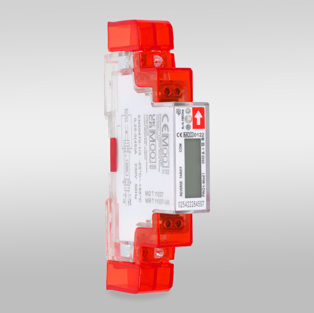
Inepro Metering PRO1-Mod
Power and energy meter
The PRO1-Mod is Inepro's one-module (17.5 mm), single-phase DIN-rail kWh meter for direct connection at 5(45) A, with an RS-485 Modbus RTU port on terminals 23 (A) and 24 (B). It shares the PRO380's register layout: Inepro prints the addresses in hexadecimal and sends every measurement as a two-register IEEE-754 float, high word first, in V, A, kW or kWh. Rows marked for the PRO380 only, such as L2, L3 and per-phase energy, do not apply.
Compatibility
Compatible with EpiSensor Edge over Modbus RTU
Inepro documents Modbus RTU over RS-485 for the PRO1-Mod and publishes an FC03 register map with hexadecimal addresses and Float32 ABCD values. Edge reads the meter as a Modbus RTU client through a ZMB-31 Modbus Interface or the Gateway's serial port.
PRO1-Mod (article 0254, 5(45) A), using the register map in PRO1 user manual version 302. Site check: compare the first voltage read with the display before adding more points. The PRO1-S, PRO1-2T and PRO1-Mb have no Modbus port, and rows marked PRO380 only do not apply. Read-only monitoring.
Connect it with
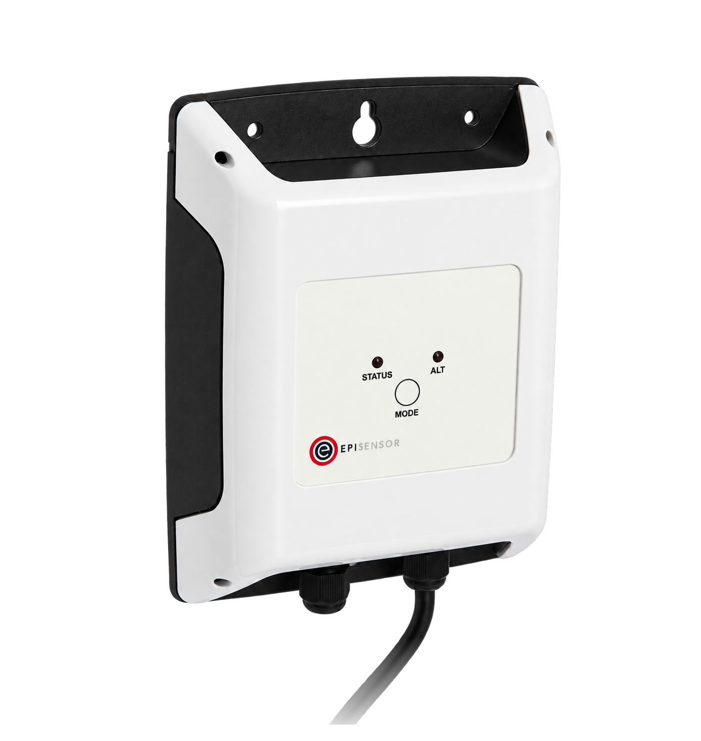
For a PRO1-Mod in a board where a wireless link avoids a new data cable
- Modbus
- Wireless
- Edge
- Platforms
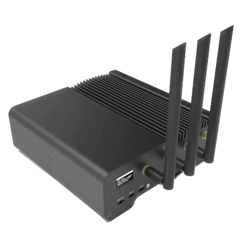
When the meter is in the same panel as a Gateway with an RS-485 serial interface
- Modbus
- Edge
- Platforms
Models
| Models | Interface | Route into Edge |
|---|---|---|
| PRO1-Mod (article 0254) | Direct connection, 5(45) A; RS-485 Modbus RTU on terminals 23 (A) and 24 (B); S0 output on 20 and 21 | Read the Appendix 3 registers not marked PRO380 only, with FC03 on the serial path. |
| PRO1-S, PRO1-2T and PRO1-Mb | Same housing; terminals 23 and 24 are unused on the PRO1-S, a 230 V tariff input on the PRO1-2T and M-Bus (EN 13757-3) on the PRO1-Mb | No Modbus port, so the register map in this guide does not apply. |
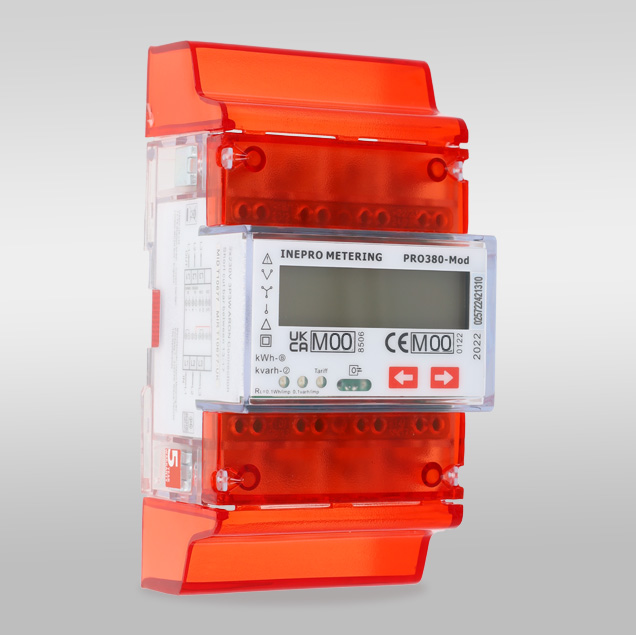
| PRO380-Mod | Three-phase sibling with the same register layout | Use its own guide. The PRO1 reads voltage at 0x5000 and current at 0x500A; L2, L3 and per-phase rows belong to the PRO380. |
Specifications
A one-module meter for a single-phase final circuit, tenant supply, charge point or small PV feed. It counts forward and reverse active and reactive energy on two tariffs, carries MID class B approval and has a programmable S0 output and five combination codes for the displayed total.12
- Exact version
- PRO1-Mod, article 0254.1
- Voltage
- Nominal 230 V AC; operating 184 to 253 V AC; 50 Hz and 60 Hz.2
- Accuracy and approval
- Class B (1%) to EN 50470-1/3. EU type-examination certificate T11037 revision 3 (NMi Certin, valid until 3 April 2027) and UK certificate T11037-UK revision 1; the product page lists MID and MIR.12
- RS-485
- Modbus RTU with 16-bit CRC on terminals 23 (A) and 24 (B). Modbus ID 1 to 247 (default 1). Default 9600 bit/s, 8 data bits, even parity, 1 stop bit; 4800, 2400 or 1200 bit/s and no or odd parity can be set.2
- Bus
- Up to 60 meters per bus and 1000 m in the manual.2
- Other interfaces
- S0 output on 20 (+) and 21 (-), 5 to 27 V DC, 100 mA, 10,000 to 0.01 imp/kWh; test LED at 10,000 imp/kWh; infrared port to IEC 62056-21.2
- Mounting
- One module on a 35 mm DIN rail: 17.5 mm wide, 90 mm high (117 mm with the covers), 63 mm deep; 0.08 kg.2
Interface
Documented measurements and integration boundaries for PRO1-Mod.
- Addresses are hexadecimal PDU addresses: 0x5000 is sent as 50 00 (decimal 20480). Read every point with FC03.
- Voltage at 0x5000 and L1 voltage at 0x5002: two registers, Float32 ABCD (high word first), V.
- Grid frequency at 0x5008: two registers, Float32 ABCD, Hz.
- Current at 0x500A and L1 current at 0x500C: two registers, Float32 ABCD, A.
- Total active power at 0x5012 (kW), total reactive power at 0x501A (kvar), total apparent power at 0x5022 (kVA) and power factor at 0x502A: Float32 ABCD.
- Total active energy at 0x6000, forward active energy at 0x600C and reverse active energy at 0x6018: Float32 ABCD, kWh, each followed by its T1 and T2 counters.
- Total, forward and reverse reactive energy at 0x6024, 0x6030 and 0x603C: Float32 ABCD, kvarh, each followed by T1 and T2.
- Identity and settings: serial number at 0x4000 (two registers, hex), meter code at 0x4002, Modbus ID at 0x4003, software version at 0x4007 (Float32), combination code at 0x400F, error code at 0x4015, power down counter at 0x4016, active tariff at 0x6048 and the resettable day counter at 0x6049 (Float32, kWh).
- Rows marked PRO380 only in this manual (L2 and L3 values, per-phase power and energy, CT ratio at 0x400C and CT mode at 0x401F) do not apply. Do not poll them on a PRO1-Mod.
Assessment
PRO1-Mod (article 0254, 5(45) A), using the register map in PRO1 user manual version 302 as a best-effort starting point. Compare the first read with the meter display. The PRO1-S, PRO1-2T and PRO1-Mb, and rows marked PRO380 only, are outside this guide. Read-only monitoring.
- InteroperabilityWell supported
- Inepro names Modbus RTU on RS-485 for the PRO1-Mod and publishes function codes, register lengths, units, data types and a hexadecimal address convention shown by its own command examples.12
- AccuracySupported with conditions
- Class B (1%) single-phase metering to 45 A with voltage, current, power and power factor, and separate forward and reverse active and reactive energy on two tariffs. The displayed total depends on the combination code.12
- SecurityNot yet assessed
- Program mode 3 on the display has a four-digit password (default 0000), but the manual does not describe access control on the Modbus port, which accepts documented configuration writes.2
- ReliabilitySupported with conditions
- Data is retained for more than ten years without power, a power-down counter records outages, and the display reports EEPROM and program checksum errors. Treat failed reads as missing data.2
- RuggednessSupported with conditions
- Rated -25 to +55 °C in operation, IP51 and protective class II, for indoor use in a suitable enclosure with surge protection where surges are frequent.12
- ScalabilitySupported with conditions
- Modbus IDs 1 to 247 and up to 60 meters per bus over 1000 m are documented, at a fixed 8 data bits and 1 stop bit.2
Setup
Read voltage from hexadecimal address 0x5000
PRO1 user manual version 302, Appendix 3, lists Voltage at register address 5000 with function code 03, two registers, unit V and data type Float ABCD. Use that map as the starting point and compare the result with the display.
- Request
- 01 03 50 00 00 02 D5 0B: Modbus ID 1, FC03, address 0x5000, two registers, RTU CRC.
- Address convention
- The table address is hexadecimal and goes on the wire as printed, as the manual's own write example 01 06 4003 000A shows. 0x5000 is decimal 20480 as a zero-based PDU address; a client that numbers registers from one shows it as 20481. Do not send decimal 5000.
- Synthetic response
- 01 03 04 43 66 00 00 0F A8: four data bytes, 43 66 00 00.
- Decode
- Float ABCD means high word first, high byte first: 0x43660000 as an IEEE-754 Float32 is 230.0 V. No scaling factor applies.
- Acceptance
- Keep the point when it agrees with the voltage on the meter display at the same time. If it does not, check the Modbus ID, address convention and installed version before adding more points.
Acceptance: The response bytes are a synthetic decoder check, not a captured meter reply. A real reply must agree with the display before current, power and energy points are enabled.
-
Identify the meter version
Read PRO1-Mod from the front label and record the software version and serial number shown on the display.
-
Read the serial settings without changing them
Program mode 1 on the display shows the Modbus ID, baud rate and parity read-only. The defaults are ID 1, 9600 bit/s, 8 data bits, even parity and 1 stop bit. Enter the same values in the Edge serial client.
-
Wire the RS-485 pair
Connect A to terminal 23 and B to terminal 24 and give each meter on the bus its own Modbus ID. The manual asks for a 120 ohm, 0.25 W resistor across 23 and 24 at the meter when it is tested through a serial converter.
-
Make one voltage read
Send FC03 to address 0x5000 for two registers and decode the Float32 high word first, as in the worked read below. Compare the result with the voltage on the display.
-
Add the points you need
Add current, power and energy registers from the same appendix, skipping rows marked PRO380 only. Log forward and reverse energy separately when export is possible, and keep FC06 and FC16 writes out of the polling configuration.
Common questions
- Is 5000 a decimal register number?
- No. Inepro prints the PRO1 addresses in hexadecimal, which is why the map has entries such as 400B and 501A. Send 0x5000, decimal 20480, as the PDU address. A tool that asks for one-based register numbers needs 20481.2
- Why do some registers in the map not answer?
- The PRO1 manual prints the same table as the three-phase PRO380 and marks the rows that only the PRO380 has: L2 and L3 voltage and current, per-phase power and energy, the CT ratio and the CT mode. A PRO1-Mod reads its voltage at 0x5000 and its current at 0x500A; leave the marked rows out.2
- Which energy register measures consumption?
- The combination code sets how the meter calculates the total active energy it displays: C-01 counts forward only, C-04 reverse only, C-05 adds forward and reverse, C-06 subtracts forward from reverse, and C-09 and C-10 subtract reverse from forward. Compare 0x6000 with the display. Forward active energy at 0x600C and reverse active energy at 0x6018 are separate counters; read those two when a site can export.2
- Does the map include writable registers?
- Yes. The manual documents FC06 and FC16 writes for the Modbus ID, baud rate, parity, S0 rate, combination code, LCD cycle time, tariff, power down counter and the resettable day counter. A monitoring configuration should read with FC03 only.2
- Does a 32-bit float energy counter lose resolution?
- Yes, gradually. A Float32 holds about seven significant digits: above about 131,000 kWh the counter moves in steps of about 0.016 kWh, and above about 1,050,000 kWh in steps of 0.125 kWh. Store each value as received and calculate consumption over intervals rather than from tiny differences.2
Related devices
More from Inepro Metering
Sources
- PRO1-Mod electricity meter product page, article 0254 (opens in a new tab)
- PRO1 series MID/MIR user manual version 302 (PRO1-S, PRO1-2T, PRO1-Mb, PRO1-Mod), with Appendix 3 Modbus register map (opens in a new tab) (PDF)
Further reading
Product names and trademarks belong to their owners. Publication does not imply endorsement or a commercial relationship.