Iskra MC 7x0A
Power and energy meter
The MC 7x0A family shares one 96 mm housing and one Modbus map: the MC 740 is a multifunction meter, the MC 750 adds an 8 MB recorder and the MC 770 is a class A power quality analyser to EN 61000-4-30. Iskra's user manual version 1.01 covers hardware version D and above, marked MC 7x0A on the side label. The main port COM1 is ordered as RS232/RS485 or as Ethernet and USB, and a second RS485 port can be added as I/O module 3/4. Iskra prints register addresses from the 30000 memory reference and packs most readings as a power-of-ten exponent byte and a 24-bit value in two registers, so every reading carries its own scale.
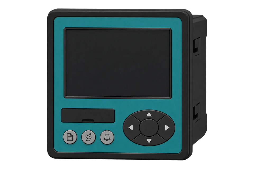
Compatibility
Compatible with EpiSensor Edge over Modbus RTU or Modbus TCP
The MC 740, MC 750 and MC 770 are compatible with EpiSensor Edge over Modbus RTU on an RS485 port (COM1 ordered as RS232/RS485, or COM2 as I/O module 3/4), read through a ZMB-31 Modbus Interface or a Gateway serial port, and over Modbus TCP on port 502 of the Ethernet and USB option. Iskra publishes the main measurement registers, their types and the decoding of each type in appendix A of the user's manual.
MC 740, MC 750 and MC 770 marked MC 7x0A (hardware version D and above), read with appendix A of user's manual version 1.01. Site check: read frequency at table address 30105 (wire address 0x0069) and compare it with the supply. Read-only monitoring: no writes to settings, resets, tariffs, digital outputs or passwords.
Connect it with


For a meter in a switchboard where a wireless link avoids running a data cable back to the Gateway
- Modbus
- Wireless
- Edge
- Platforms
When the Gateway sits near the meter, or several meters share one wired RS485 bus
- Wired
- Edge
- Platforms
When COM1 was ordered as Ethernet and USB (ordering code E)
- Modbus
- Edge
- Platforms
Models
| Models | Interface | Route into Edge |
|---|---|---|
| MC 740 (MC 740A) | Multifunction meter, class S measuring accuracy, 32 alarms, up to four inputs or outputs, COM1 RS232/RS485 or Ethernet and USB | Read the input registers in appendix A over RS485 or Modbus TCP. |
| MC 750 (MC 750A) | Network recorder with the MC 740's measurements plus an 8 MB internal memory for up to 64 recorded quantities and 32 alarms | Same registers and routes. Edge reads the present values; the internal recorder is downloaded with Iskra's MiQen software. |
| MC 770 (MC 770A) | Power quality analyser, class A to EN 61000-4-30, EN 50160 reports, flicker and interharmonics | Same measurement registers, plus the flicker and interharmonic registers. Edge reads the present values; EN 50160 reports stay in the meter and MiQen. |
| MC 740, MC 750 or MC 770 without the MC 7x0A label | Earlier hardware, documented in a different Iskra manual | Use the manual for that hardware before mapping points: this guide's addresses come from the MC 7x0A manual only. |
Specifications
The MC 7x0A family samples 4 voltage and 3 current channels at 32 kHz with automatic range selection up to 12.5 A and 1000 V rms, and measures more than 140 quantities including harmonics to the 63rd, unbalance and, on the MC 770, flicker. Up to three communication ports carry Modbus and DNP3: COM1 as RS232/RS485 or Ethernet and USB, and an optional RS232 or RS485 COM2.12
- Ordering code
- MC 740, MC 750 or MC 770 followed by: nominal frequency (S 50/60 Hz, A 400 Hz, B 16 2/3 Hz), auxiliary supply (U universal, D 110 V AC, E 230 V AC, F 400 V AC), COM1 (T RS232/RS485 terminal, R RS232/RS485 DB9, E Ethernet and USB), I/O module 1/2, I/O module 3/4 (including G RS232 COM2 and C RS485 COM2), RTC backup (C supercap, B battery) and current connection (T through-hole, C screw terminal).234
- Accuracy
- To IEC 61557-12: active energy class 0.5S on the MC 740 and MC 750 and 0.2S on the MC 770; active power 0.2; rms current 0.2 (MC 770: 0.1); phase voltage 0.2 (MC 770: 0.1, class A); frequency 0.02. Class S to EN 61000-4-30 on the MC 740 and MC 750, class A on the MC 770.1
- Voltage inputs
- 4 channels, the fourth for earth to neutral; nominal 500 V L-N, 866 V L-L; maximum measured 600 V L-N, 1000 V L-L continuously; 1.2 × UN permanently, 2 × UN for 10 s.1
- Current inputs
- 3 channels, nominal 1 A or 5 A, maximum measured 12.5 A, 15 A continuous thermal, 300 A for 1 s; VT and CT ratios set in the meter.1
- Communication
- RS485 (1000 m) or RS232 on terminals 21 to 25 or a DB9, 2400 to 115200 bit/s, Modbus RTU and DNP3 detected automatically; factory address 33, 115200 bit/s, no parity, 8 data bits, 2 stop bits. Ethernet 10/100 Mb/s with Modbus TCP and DNP3 on port 502, DHCP by default; USB 2.0.1
- Auxiliary supply
- Universal 48 to 276 V AC (40 to 65 Hz) or 20 to 300 V DC, or AC 110, 230 or 400 V; under 8 VA with all I/O.12
- Housing
- 96 × 96 × 96.5 mm (101.5 mm with through-hole CTs), 92 × 92 mm panel cut-out, PC/ABS to UL 94 V-0, 550 g; IP40 front with the memory slot cover, IP20 rear.1
- Environment
- Operating -10 to 55 °C (K55 to EN 61557-12), storage -40 to +70 °C, 75% r.h. without condensation.1
- Safety and EMC
- Protection class II to EN 61010-1:2010, 600 V rms CAT II or 300 V rms CAT III, pollution degree 2; EN 61326-1:2013 for industrial environments.1
Interface
Documented measurements and integration boundaries for MC 7x0A.
- Iskra states that the memory reference for input and holding registers is 30000 and 40000, and prints each address as that reference plus the register offset. Subtract 30000 for the zero-based address on the wire: frequency at 30105 is 0x0069. A client that numbers input registers from one takes the table value plus one. Read the measurements with function 04.
- T5 (unsigned) and T6 (signed) take two registers: the top byte is a signed power-of-ten exponent and the remaining 24 bits are the value. Iskra's example stores 123456 × 10⁻³ as FD01 E240. The table has no unit column, so check the first decoded value of each quantity against the display before choosing units in Edge.
- Frequency at 30105 (hex 0069), T5. Phase voltages U1, U2 and U3 at 30107, 30109 and 30111 (hex 006B, 006D, 006F) and their average at 30113 (hex 0071); line voltages U12, U23 and U31 at 30118, 30120 and 30122 (hex 0076, 0078, 007A) and their average at 30124 (hex 007C); all T5.
- Currents I1, I2 and I3 at 30126, 30128 and 30130 (hex 007E, 0080, 0082), calculated neutral current at 30132 (hex 0084), average current at 30136 (hex 0088) and total current at 30138 (hex 008A); all T5.
- Total active power at 30140 (hex 008C) and phase active power at 30142, 30144 and 30146 (hex 008E, 0090, 0092), T6 signed; total reactive power at 30148 (hex 0094), T6; total apparent power at 30156 (hex 009C), T5.
- Total power factor at 30164 (hex 00A4) and phase power factor at 30166, 30168 and 30170 (hex 00A6, 00A8, 00AA), T7: the first byte flags import or export (00 or FF), the second inductive or capacitive (00 or FF), and the second register is the value with four decimal places.
- Voltage THD U1 to U3 at 30182 to 30184 (hex 00B6 to 00B8) and current THD I1 to I3 at 30188 to 30190 (hex 00BC to 00BE), one register each, T16, unsigned with two decimal places. Internal temperature at 30181 (hex 00B5), T2.
- Energy counters E1 to E4 at 30406, 30408, 30410 and 30412 (hex 0196, 0198, 019A, 019C), T3 signed 32-bit, each with its own exponent register, T2, at 30401 to 30404 (hex 0191 to 0194). The counter is the value times ten to the power of its exponent; Iskra's energy settings describe that exponent as a power of ten of Wh, so -3 is mWh and 4 is 10 kWh. Tariff counters follow from 30414 and the active tariff is at 30405.
- Which quantity each energy counter holds (import or export, active, reactive or apparent, total or one phase) is a setting of the meter. Read the counter settings in MiQen or on the display before labelling a counter in Edge, and after any change Iskra says the counters should be reset, so earlier recorded values no longer compare.
- Maximum demand since the last reset: positive real power at 30542 (hex 021E), negative real power at 30548, apparent power at 30536 and phase currents at 30518, 30524 and 30530. Dynamic demand values from 30502 to 30517.
- The appendix lists the main registers only; Iskra says the other registers are subject to change and points to its web site for the complete table. Settings from 40143 (connection mode, CT and VT values in T4) need a level 2 password to change, and digital outputs can be driven by writing Modbus registers. Keep every write out of a monitoring poll.
Assessment
MC 740, MC 750 and MC 770 marked MC 7x0A (hardware version D and above), read with appendix A of user's manual version 1.01. Site check: read frequency at table address 30105 (wire address 0x0069) and compare it with the supply. Read-only monitoring: no writes to settings, resets, tariffs, digital outputs or passwords.
- InteroperabilitySupported with conditions
- Iskra documents Modbus RTU and Modbus TCP on every port and publishes the main measurement registers with start and end addresses, types and the decoding of each type. The appendix lists main registers only, the offset is implied by the 30000 memory reference, and the self-scaling T5, T6 and T7 types need a client that applies the exponent or flag bytes.1
- AccuracyWell supported
- Active energy class 0.5S (MC 740 and MC 750) or 0.2S (MC 770) to IEC 61557-12, class S or class A to EN 61000-4-30, four-quadrant energy, harmonics to the 63rd and 1 A or 5 A inputs with automatic ranging to 12.5 A.124
- SecurityLimited
- Two password levels protect resets and settings, but the factory password AAAA does not limit access, and a backup password tied to the serial number is available from Iskra. Modbus RTU and TCP carry no encryption, and digital outputs can be driven over Modbus. Set passwords and keep the network private.1
- ReliabilitySupported with conditions
- EMC to EN 61326-1 for industrial environments with stated influence limits, a real-time clock backed by a supercap or battery, NTP synchronisation and a watchdog output option. Iskra warns that energy setting changes invalidate earlier recorded values until the counters are reset.12
- RuggednessSupported with conditions
- Rated -10 to 55 °C (K55), storage -40 to +70 °C, 75% r.h. without condensation, IP40 front and IP20 rear, protection class II. It is a panel instrument and needs a switchboard door or enclosure.1
- ScalabilitySupported with conditions
- RS485 runs to 1000 m at up to 115200 bit/s with addresses 1 to 247, and port 502 accepts several Modbus TCP clients. Every meter ships at address 33, so each one on a shared bus must be readdressed first.1
Setup
Read frequency at 30105, then energy counter E1 with its exponent
Appendix A of Iskra's MC 7x0 user's manual version 1.01 lists Frequency at 30105 to 30106 as type T5, Energy Counter 1 Exponent at 30401 as type T2, and Counter E1 at 30406 to 30407 as type T3, with 30000 as the memory reference for input registers. The meter's factory Modbus address is 33 (0x21).
- Function
- FC04, read input registers
- Address
- Table 30105. Send 0x0069 (105, zero-based: 30105 minus the 30000 reference). A client with one-based 3xxxx numbers enters 30106.
- Request
- 21 04 00 69 00 02 A6 B7: address 33, FC04, address 0x0069, two registers, RTU CRC.
- Synthetic response
- 21 04 04 FE 00 13 88 E6 F8: data FE 00 13 88, exponent FE = -2 and value 00 13 88 = 5000, so 5000 × 10⁻² = 50.00 Hz.
- Energy read
- 21 04 01 91 00 01 66 BB reads the E1 exponent at 0x0191 (table 30401); synthetic response 21 04 02 00 01 F9 37 gives exponent 1. Then 21 04 01 96 00 02 97 7B reads Counter E1 at 0x0196 (table 30406); synthetic response 21 04 04 00 12 D6 87 64 41 gives 0x0012D687 = 1234567, so 1234567 × 10¹ Wh = 12345.67 kWh.
- Acceptance
- Keep the points when frequency is close to the supply and the scaled counter agrees with the energy screen for the quantity E1 is set to measure. A counter read without its exponent is wrong by a power of ten.
Acceptance: The response bytes are a synthetic decoder check, not a captured meter reply. Over Modbus TCP the same function, addresses and decode apply, with the unit identifier set to the device address.
-
Identify the hardware and the port
Check the side label for MC 7x0A, which this register map covers, and read the ordering code: COM1 T or R is RS232/RS485, E is Ethernet and USB, and C in the I/O module 3/4 position is an extra RS485 port.
-
Set a unique address
Every meter leaves the factory at Modbus address 33. Change it under Settings, Communication before several meters share one RS485 bus, and note the speed, parity and stop bits (115200 bit/s, no parity, 8 data bits, 2 stop bits by default).
-
Wire RS485 or connect Ethernet
For RS485, wire A to terminal 21 and B to terminal 22 and leave the RS232 terminals unused. For Ethernet, fix or reserve the meter's DHCP address and connect Edge to port 502 with the unit identifier set to the device address.
-
Read frequency first
Read two input registers with function 04 from wire address 0x0069 (table 30105) and decode them as T5. The result should be close to 50 Hz or 60 Hz; a value that makes no sense usually means the exponent byte was ignored or the address is one register out.
-
Add the measurements
Add voltages, currents and power in register pairs from the appendix A tables, decoding T5, T6 and T7 values with their own exponent or flag bytes, and compare each new quantity with the display.
-
Map the energy counters
Check which quantity each counter E1 to E4 is set to measure, read each counter with its exponent register and compare the scaled result with the energy screen. Do not reset counters or change energy settings from Edge.
Common questions
- Why send 0x0069 when the MC 750 table says 30105?
- Iskra's appendix A states that the memory reference for input registers is 30000, so the printed address is the reference plus the register offset. 30105 is offset 105, or 0x0069, read with function 04. A client that takes one-based 3xxxx numbers subtracts 30001, so it needs 30106 to reach the same register.1
- How is a T5 or T6 value from the MC 7x0A decoded?
- Read both registers in one request. The top byte of the first register is a signed 8-bit exponent and the remaining 24 bits are the value, unsigned for T5 and signed for T6. Multiply the value by ten to the power of the exponent. Iskra's examples are FD01 E240 for 123456 × 10⁻³ (T5) and FDFE 1DC0 for -123456 × 10⁻³ (T6).1
- How do I scale the MC 7x0A energy counters?
- Each counter E1 to E4 at 30406 to 30413 is a signed 32-bit value with its own exponent register at 30401 to 30404. The reading is the counter times ten to the power of the exponent, in Wh according to Iskra's description of the energy prefix (-3 is mWh, 4 is 10 kWh). The exponent follows the meter's common and individual counter resolution settings, so read it with the counter rather than fixing a scale.1
- What are the MC 750 factory communication settings?
- Serial COM1: Modbus address 33, 115200 bit/s, no parity, 8 data bits and 2 stop bits, with Modbus RTU and DNP3 detected automatically. Ethernet: DHCP, Modbus TCP on the fixed port 502, which allows several connections, and a terminal port 10001 that allows only one.1
- Can Edge and MiQen read the MC 7x0A at the same time over Ethernet?
- Yes on port 502, which accepts multiple connections. A connection to the user-defined terminal port, used for firmware updates, blocks all other connections including port 502, and a USB cable on COM1 takes priority and ends the Ethernet connection until it is unplugged.1
- Does Edge read the MC 770 power quality reports?
- No. Edge reads present values from the input registers, including frequency, voltages, currents, power, THD and the flicker registers. The EN 50160 reports and recorded data are stored in the meter's memory and retrieved with Iskra's MiQen software or the memory card.14
Related devices
More from Iskra
Sources
- Power Monitoring Device MC 7x0 user's manual, version 1.01 (October 2021), valid for hardware version D and above marked MC 7x0A, with appendix A Modbus communication protocol (opens in a new tab) (PDF)
- MC 750 Network Recorder technical documentation, version 1.02 (June 2020), with the ordering code (opens in a new tab) (PDF)
- MC 740 Multifunction Meter technical documentation, version 1.03 (June 2020) (opens in a new tab) (PDF)
- MC 770 Power Quality Analyzer technical documentation, version 1.07 (June 2020) (opens in a new tab) (PDF)
Further reading
Product names and trademarks belong to their owners. Publication does not imply endorsement or a commercial relationship.