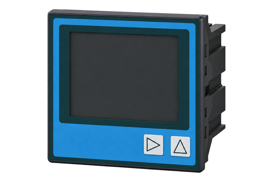
Iskra WM3M4
Power and energy meter
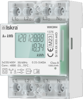
The WM3M4 is Iskra's three-module, direct-connected three-phase meter for up to 40 A, MID approved for class B and built for EV charging points. Every meter has an RS-485 port and an infrared port, both speaking Modbus RTU, and Iskra's user manual prints the full register table. Two things set it apart from most meters: addresses are written as the 30000 memory reference plus the register offset, and most measurements use Iskra's T5, T6 and T7 types, where the top byte is a signed power-of-ten exponent rather than a fixed scale. The WM3M4C adds digital signing of charging data on the same measurement registers.
Compatibility
Compatible with EpiSensor Edge over Modbus RTU
Iskra documents Modbus RTU on the RS-485 port of every WM3M4 and WM3M4C and publishes the input register table with addresses, lengths and data types. This is documented compatibility, without a physical Edge test.
Iskra WM3M4 and WM3M4C (V2), read with appendix 9 of user manual version 2.13, valid from firmware 2.12. The measurement addresses used here are the same in manual version 1.14 for earlier meters. Read-only monitoring of the input registers: no writes to settings, passwords, the Change Lock control or the WM3M4C charging-transaction registers.
Connect it with
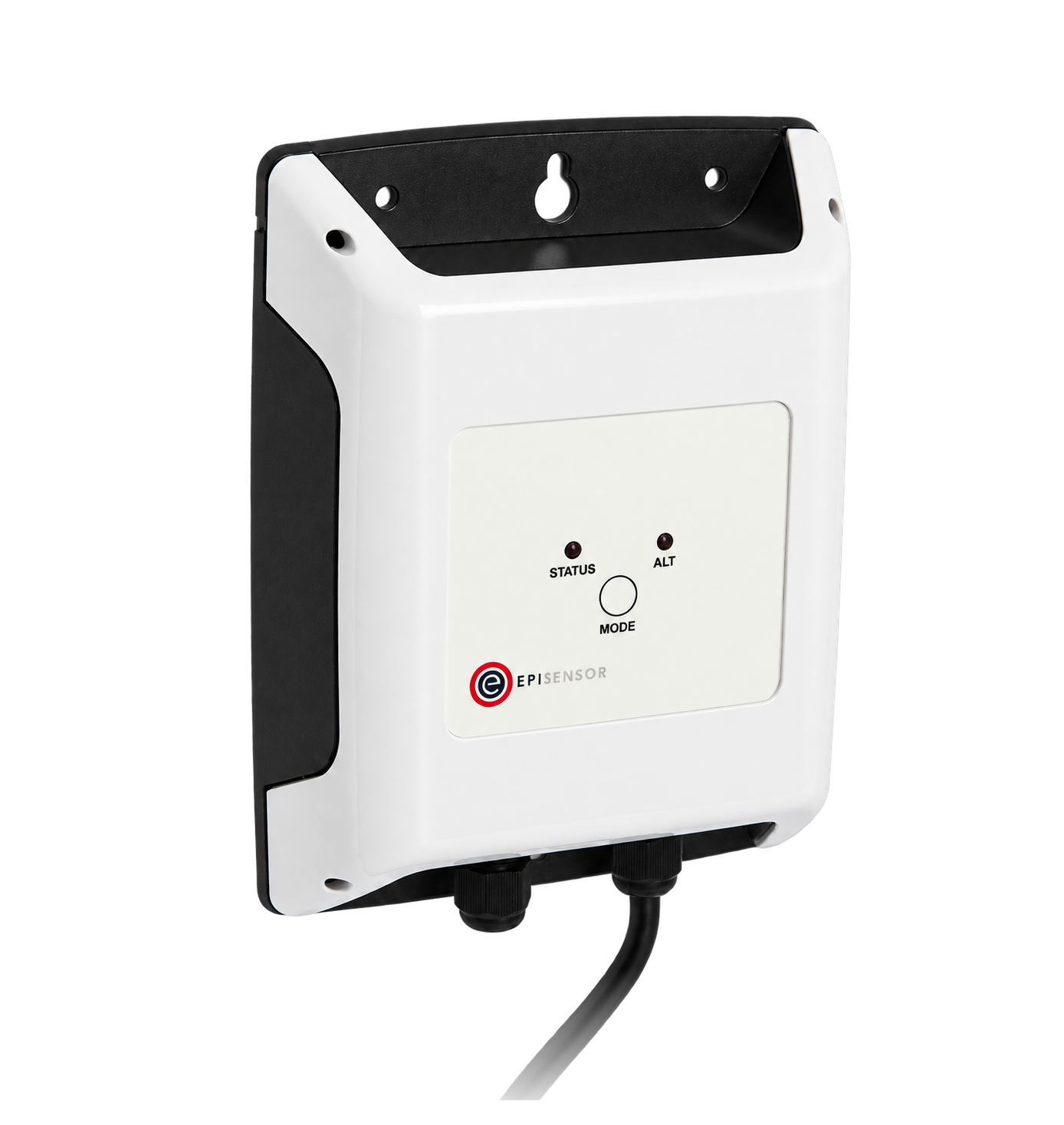
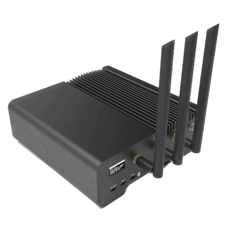
For a WM3M4 or WM3M4C wired on its RS-485 terminals 16 (A) and 15 (B)
- Modbus
- Wireless
- Edge
- Platforms
Models
| Models | Interface | Route into Edge |
|---|---|---|
| WM3M4 (V2) | RS-485 Modbus RTU on terminals 16 (A) and 15 (B); infrared Modbus RTU through the WM-USB adapter | Read the input registers in appendix 9 of manual version 2.13 over RS-485. |
| WM3M4C (V2) | Same ports and measurement registers, plus digital signing of charging transactions (ECDSA secp256r1) | Read the same measurement registers. Leave the transaction, time and signature registers from 47000 to the charging station controller. |
| WM3M4 and WM3M4C before firmware 2.12 | Same RS-485 port; documented in manual version 1.14 | The measurement addresses used here are unchanged, but calculated neutral current at 30132 was added in firmware 2.12. Read the software reference at 30013 and use manual 1.14 for an older meter. |
Specifications
The WM3M4 suits a three-phase or single-phase EV charging point, sub-circuit or tenant supply up to 40 A where a MID-approved meter with a local display and RS-485 readings is wanted. It connects directly, with no current transformers, and draws its supply from the measured voltage.1
- Models
- WM3M4 and WM3M4C. The WM3M4C adds digital signing of charging transactions and PTB approval for EV charging stations.12
- Connection
- Direct connection to a four-wire three-phase network, or single-phase on L3. The neutral must be connected.1
- Current
- Reference 5 A, maximum 40 A, minimum 0.25 A, transitional 0.5 A, starting current 20 mA.1
- Voltage and frequency
- 3 × 230/400 V (-20% to +15%), 50 Hz or 60 Hz. Consumption below 8 VA and 0.6 W per phase.1
- Accuracy
- Active energy class 1 (EN 62053-21) and class B (EN 50470-3), with MID approval for class B. Voltage and current ±1%, active power ±1%, reactive and apparent power ±2%, frequency ±0.5%, within the stated current ranges.1
- RS-485
- Modbus RTU on terminals 16 (A) and 15 (B); 1200 to 115200 bit/s (default 115200), 8 data bits, no, odd or even parity, one or two stop bits (default 8N1). Default address 33, settable from 1 to 247.1
- Infrared port
- Modbus RTU at 19200 bit/s 8N1, address 33, through the WM-USB adapter. Its settings are fixed.1
- Terminals
- Main terminals 2.5 to 25 mm² rigid (16 mm² flexible), M5, 3 Nm; communication terminals 1 to 2.5 mm², M3, 0.7 Nm.1
- Housing
- Three DIN modules on a 35 mm rail, 53.6 × 84 × 69.4 mm, 228 g. IP50 (IP51 when mounted in an IP51 cabinet), protection class II, 300 V CAT III.1
- Environment
- Operating -25 to +70 °C, storage -30 to +80 °C, non-condensing humidity, indoor use, mechanical class M1 and electromagnetic class E2.1
Interface
Documented measurements and integration boundaries for WM3M4.
- Iskra prints each address as the 30000 memory reference plus the register offset, and lists register 30000 itself (device group). Subtract 30000 for the zero-based address sent on the wire; a client that expects one-based 3xxxx numbers enters the table value plus one. Read the input registers with function 04.
- T5 (unsigned) and T6 (signed) are two registers: the top byte of the first register is a signed power-of-ten exponent and the remaining 24 bits are the value. Iskra's example stores 123456 × 10⁻³ as FD01 E240. The table has no unit column, so check the first decoded value of each quantity against the display or a known value before relying on base units (Hz, V, A, W).
- Frequency at 30105 to 30106: T5, Hz.
- Phase voltages U1, U2 and U3 at 30107, 30109 and 30111 and line voltages U12, U23 and U31 at 30118, 30120 and 30122: two registers each, T5, V.
- Phase currents I1, I2 and I3 at 30126, 30128 and 30130: two registers each, T5, A. Calculated neutral current at 30132 from firmware 2.12.
- Total active power at 30140 and phase active power at 30142, 30144 and 30146: two registers each, T6 signed, W. Total reactive power at 30148 (T6) and total apparent power at 30156 (T5).
- Total power factor at 30164 and phase power factor at 30166, 30168 and 30170: T7, where the first byte flags import or export (00 or FF), the second inductive or capacitive (00 or FF), and the second register is the value with four decimal places.
- Voltage THD at 30182 to 30184 and current THD at 30188 to 30190: one register each, T16, unsigned with two decimal places, %.
- Energy counter 1 (imported active energy) at 30418 to 30419 and counter 2 (exported active energy) at 30420 to 30421: T3, signed 32-bit, each with its own T2 exponent register at 30414 and 30415. Counters 3 and 4 are squared-current totals for cable-loss calculation, not energy.
Assessment
Iskra WM3M4 and WM3M4C (V2), read with appendix 9 of user manual version 2.13, valid from firmware 2.12. The measurement addresses used here are the same in manual version 1.14 for earlier meters. Read-only monitoring of the input registers: no writes to settings, passwords, the Change Lock control or the WM3M4C charging-transaction registers.
- InteroperabilitySupported with conditions
- Iskra publishes Modbus RTU on the RS-485 port with addresses, lengths and data type definitions for every measurement, and no vendor software is needed to read it. The address offset is implied by the 30000 memory reference rather than stated, and the self-scaling T5, T6 and T7 types need a client that applies the exponent byte.1
- AccuracySupported with conditions
- Class 1 and MID class B active energy with per-phase voltage, current, power, power factor and THD. Direct connection limits it to circuits of 40 A or less, and only active energy is counted: the other two counters are squared-current totals for cable losses.1
- SecuritySupported with conditions
- Settings need a level 2 password entered through holding register 40001, a permanent Change Lock control blocks further changes to key settings, and the energy counters are fixed and cannot be reset. The factory password AAAA does not limit access, and the RS-485 link has no encryption, so set a password and keep the bus private.12
- ReliabilitySupported with conditions
- The meter is powered from the measured voltage, keeps settings and charging events in EEPROM, reports invalid phase measurements at 30101 and checksum errors at 30400, and is built to EN 62052-11, EN 62059-32-1 durability testing and CLC/TR 50579 immunity. It has no battery, so the clock is lost on a power cut; treat failed reads as missing data.1
- RuggednessSupported with conditions
- Rated -25 to +70 °C, IP50 (IP51 in a suitable cabinet), protection class II, 300 V CAT III, M1 and E2, with documented terminal sizes and torques. Indoor use inside an enclosure.1
- ScalabilitySupported with conditions
- Addresses 1 to 247 and speeds up to 115200 bit/s are documented, but every meter ships at address 33 and must be readdressed before it joins a shared bus. Iskra does not state a maximum number of meters per segment.1
- LifecycleSupported with conditions
- Iskra publishes a product change notification listing every firmware change from 2.05 to 2.12, keeps the manual for earlier meters available beside the current one, and makes the firmware version readable at 30013. No support period or end-of-sale date is stated.123
Setup
First read: frequency with the 30000 offset
This uses appendix 9 of Iskra's WM3M4 and WM3M4C user manual, version 2.13 (September 2024, valid from firmware 2.12). Frequency is listed at input registers 30105 to 30106 as type T5.
- Function
- FC04, read input registers
- Convention check
- Read one register at zero-based address 0x0000. The reply should be 4 (device group WM). As an RTU frame to the factory address 33: 21 04 00 00 00 01 36 AA.
- Address
- Table 30105. Send 0x0069 (105, zero-based: 30105 minus the 30000 reference). A client with one-based 3xxxx numbers enters 30106.
- Request
- PDU 04 00 69 00 02, two registers. As an RTU frame to address 33: 21 04 00 69 00 02 A6 B7.
- Decode
- T5: the top byte of the first register is a signed exponent, the next 24 bits an unsigned value. Frequency = value × 10^exponent Hz.
- Example
- Data FE 00 13 88: exponent FE = -2, value 00 13 88 = 5000, so 5000 × 10⁻² = 50.00 Hz. Illustrative decode, not a captured meter reply.
- Acceptance
- Close to the nominal 50 Hz or 60 Hz supply. A value that makes no sense usually means the exponent byte was ignored or the address is one register out.
Acceptance: Keep the point when the device group reads 4 and the frequency is plausible. Then add voltages and energy and compare them with the display. Record the manual version and the firmware read from 30013 with the configuration.
-
Identify the meter and firmware
Check the front label for WM3M4 or WM3M4C. The firmware identification screen at power-up shows the main firmware version, which is also readable at input register 30013 (100 = 1.00). Manual version 2.13 is valid from firmware 2.12; record the version with the configuration.
-
Give every meter its own address
Every WM3M4 leaves the factory at Modbus address 33, so meters on a shared bus must be readdressed first. Iskra's MiQen software does this over the infrared or RS-485 port; the address is holding register 40202 (1 to 247).
-
Match the serial settings
The default is 115200 bit/s, 8 data bits, no parity and one stop bit. Enter the installed values in Edge. If the installer changes speed, parity or stop bits, those settings are only kept after the save command, so confirm them on the meter before commissioning.
-
Wire the RS-485 line
Connect A to terminal 16 and B to terminal 15 as in Iskra's connection diagram, using 1 to 2.5 mm² conductors in the M3 communication terminals. Keep the bus a single daisy chain.
-
Confirm the address convention
Read one input register at zero-based address 0 with function 04. It should return 4, the WM device group, which confirms that the table addresses are offset from 30000. Then read the model number string at 30001 to 30008.
-
Start with the frequency read
Read frequency with the example below and compare it with the supply. Then add voltages, currents, power and the energy counters with their exponent registers, checking each new point against the meter display.
Common questions
- Why send 0x0069 when the table says 30105?
- Iskra's table starts each section with a memory reference of 30000 and lists register 30000 itself as the device group, so the printed address is the reference plus the register offset. 30105 is offset 105, or 0x0069, read with function 04. A client that takes one-based 3xxxx numbers subtracts 30001, so it needs 30106 to reach the same register. Reading the device group at offset 0 (value 4) is a quick check of which convention your client uses.1
- How is a T5 or T6 value decoded?
- Read both registers in one request. The top byte of the first register is a signed 8-bit exponent and the remaining 24 bits are the value: unsigned for T5, signed for T6. Multiply the value by ten to the power of the exponent. Iskra's examples are FD01 E240 for 123456 × 10⁻³ (T5) and FDFE 1DC0 for -123456 × 10⁻³ (T6). Because the exponent travels with each reading, do not apply a fixed scale.1
- Which counters are energy, and how fine is the Modbus resolution?
- Counter 1 is imported active energy and counter 2 exported active energy; counters 3 and 4 accumulate squared current for the cable-loss calculation. All four are fixed in production and cannot be reset. Iskra states that the display shows energy in 10 Wh steps while the Modbus registers carry 1 Wh resolution, and holding register 47099 can change that to 10 Wh. Read each counter with its exponent register and check the scaled result against the kWh display before storing it.1
- Can Edge read a WM3M4C used in a charging station?
- The WM3M4C has the same measurement registers as the WM3M4. Its charging transactions, time setting and signed datasets live in the holding registers from 47000 and are driven by the charging station controller. Edge needs only the input registers; never write to the transaction, time or Change Lock control registers from Edge.1
- Is the WM3M4 approved for billing?
- Iskra's manual gives MID approval for class B to EN 50470-3 for both models, and PTB approval for EV charging stations for the WM3M4C. Treat Edge readings as monitoring data; where billing is required, use the approved meter's own register and, on the WM3M4C, its signed dataset.1
Related devices
Sources
- User's manual WM3M4 and WM3M4C, version 2.13 (September 2024, valid from firmware 2.12), K22.433.950, with appendix 9 Modbus tables (opens in a new tab) (PDF)
- Product/process change notification PCN 2024-002 (23 August 2024): WM3M4 and WM3M4C housing and firmware 2.05 to 2.12 (opens in a new tab) (PDF)
- User's manual WM3M4 and WM3M4C, version 1.14 (July 2023), K22.433.922, for meters before firmware 2.12 (opens in a new tab) (PDF)
Further reading
Product names and trademarks belong to their owners. Publication does not imply endorsement or a commercial relationship.