Sigenergy SigenStack
Commercial battery energy storage system
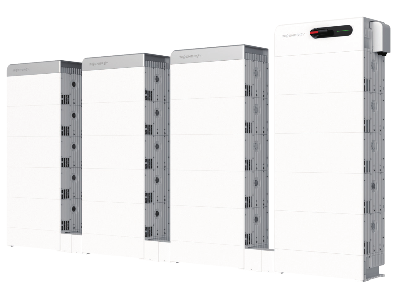
SigenStack is Sigenergy's modular C&I battery: 12.06 kWh LFP modules, 4 to 21 per system, behind a Sigen Hybrid 50 to 125 kW M1-HYA inverter. The battery modules and battery controller talk CAN to the inverter. Edge reads the inverter's Modbus TCP server on port 502, using the public Sigenergy Modbus Protocol V2.7: plant totals at slave address 247 and each inverter at its own address.
Compatibility
Compatible with EpiSensor Edge over Modbus TCP through the Sigen Hybrid inverter
Sigenergy Modbus Protocol V2.7 lists the Sigen PV 50 to 125 M1-HYA hybrid inverters, defines a Modbus TCP server on port 502 and publishes plant and inverter registers for SOC, battery power, energy and state. Edge is a Modbus TCP client and reads that server. The SigenStack modules and battery controller reach the inverter over CAN, which stays inside the Sigenergy system.
SigenStack BAT 12.0 with SigenStack BC on Sigen PV 50, 60, 80, 100, 110 or 125 M1-HYA, datasheets 20260924 and 20260709 and Modbus Protocol V2.7. M1-HYB backup models are not in the V2.7 model table. Site check: confirm with the installer that the plant answers Modbus TCP, note each inverter's slave address and compare the first reads with mySigen. Read-only monitoring; no EMS mode, power or SOC writes.
Connect it with
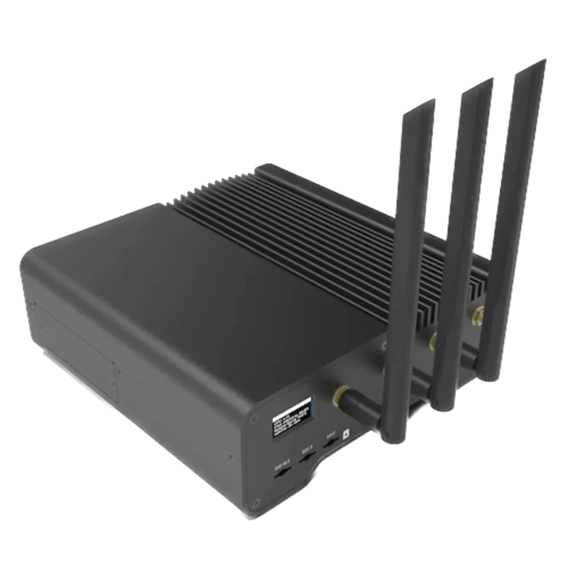
On any SigenStack system: the M1-HYA inverter that owns the battery serves plant and inverter registers
- Wired
- Edge
- Platforms
Models
| Models | Interface | Route into Edge |
|---|---|---|
| SigenStack BAT 12.0 with SigenStack BC M2-0.5C-BST, M2-1C-BST, M2-0.5C-BST-L or M2-1C-BST-L | 12.06 kWh LFP modules, 4 to 21 per system and up to 7 per stack; the battery controller talks CAN to the inverter | Read battery values from the inverter's Modbus TCP server. The battery controller has no Edge interface of its own. |
| SigenStack BC M2-0.5C | Battery controller restricted to on-grid systems with 20 or more modules at 380/400 V and no PV connected | Same inverter route. Use a BST controller for any other configuration, as the datasheet requires. |
| Sigen PV 50M1-HYA, 60M1-HYA, 80M1-HYA, 100M1-HYA, 110M1-HYA, 125M1-HYA | 50 to 125 kW hybrid inverters with WLAN, Fast Ethernet, RS485 and Sigen CommMod | Listed under Hybrid Inv. in Modbus Protocol V2.7 table 2-1. Registers marked for Hybrid Inv. apply. |
| Sigen PV M1-HYB backup inverters | Backup variants of the same power range | Not in the V2.7 model table. Obtain the Sigenergy protocol revision that lists the HYB series before using these registers on it. |
Specifications
One SigenStack system holds 4 to 21 SigenStack BAT 12.0 modules, up to 7 per stack, for a maximum of 253 kWh. A SigenStack BC battery controller sits on each stack and connects to a Sigen C&I hybrid inverter over CAN.2
- Battery module
- SigenStack BAT 12.0: LiFePO4, 314 Ah cells, 12.06 kWh per module, 105 kg, 770 / 300 / 363 mm2
- Charge and discharge rate
- 0.5C nominal, 1C maximum2
- System size
- 4 to 21 modules per system, 7 per stack; 253 kWh maximum system energy2
- Battery controller
- SigenStack BC: 180 A maximum to and from the inverter, 550 to 1,100 V operating range, CAN communication2
- Inverter power
- Sigen PV 50 to 125 M1-HYA: 50,000 to 125,000 W nominal AC; 55,000 to 137,500 W maximum battery charge and discharge; 180 A battery operating current3
- Inverter communication
- WLAN, Fast Ethernet, RS485 and Sigen CommMod (4G/3G/2G); built-in EMS for up to 100 units in parallel without a data logger3
- Modbus TCP server
- TCP server, slave mode, port 502; plant address 247, inverter addresses 1 to 246, broadcast address 01
- Battery environment
- IP66; -20 to 55 °C operating; up to 4,000 m with derating above 2,000 m; aerosol fire suppression, smoke sensor and exhaust2
- Battery standards
- IEC/EN 60730-1, UN 38.3, IEC/EN 62619, IEC/EN 63056, IEC/EN 62040, UL9540A2
Interface
Documented measurements and integration boundaries for SigenStack.
- Plant level, slave address 247, FC04: [ESS] SOC 30014 (U16, gain 10, %), plant active power 30031 (S32, gain 1000, kW), photovoltaic power 30035 (S32, gain 1000, kW), [ESS] power 30037 (S32, gain 1000, kW; positive charging, negative discharging) and plant running state 30051 (U16, Appendix 1: 0 standby, 1 running, 2 fault, 3 shutdown, 7 environmental abnormality).
- Plant level, address 247: [ESS] rated energy capacity 30083 (U32, gain 100, kWh), [ESS] SOH 30087 (U16, gain 10, %, weighted by each ESS rated capacity), and grid sensor active power 30005 (S32, gain 1000, kW; positive buying from the grid, negative selling) when grid sensor status 30004 reads 1.
- Inverter level, the inverter's own slave address 1 to 246: rated active power 30540 (U32, gain 1000, kW), running state 30578 (U16), [ESS] charge/discharge power 30599 (S32, gain 1000, kW), [ESS] battery SOC 30601 and SOH 30602 (U16, gain 10, %). Model type 30500, serial number 30515 and firmware 30525 are ASCII strings of 15, 10 and 15 registers, which Edge's Modbus client does not decode; record them at commissioning from mySigen or a Modbus tool.
- Inverter-level battery energy: [ESS] daily charge energy 30566 and daily discharge energy 30572 (U32, gain 100, kWh). Two-register values arrive high word first, as the chapter 6 example shows. The accumulated charge and discharge totals at 30568 and 30574 are 64-bit (U64, 4 registers), which Edge's Modbus client does not read; use the daily counters for daily energy and obtain accumulated totals from mySigen.
- Holding registers from 40000, including EMS work mode, Remote EMS enable 40029 and the power targets, are control registers. Leave them unwritten: battery control is outside this guide and needs the site owner's and Sigenergy's agreement.
Assessment
SigenStack BAT 12.0 with SigenStack BC on Sigen PV 50 to 125 M1-HYA, Modbus Protocol V2.7. M1-HYB backup models and holding-register control are outside this scope.
- InteroperabilitySupported with conditions
- A public Modbus TCP map on port 502 covers plant and inverter battery values with types, gains and units. The condition is the revision's conflicting function-code tables, which a first read settles.13
- AccuracySupported with conditions
- Battery power, grid-sensor power and energy counters have stated gains and signs. SOC and SOH are battery-management estimates, and grid values exist only when a grid sensor is connected.1
- SecurityLimited
- The server is plain Modbus TCP on port 502 with no authentication, and the same port accepts write commands. Restrict it to the Gateway on a protected network.1
- ReliabilitySupported with conditions
- V2.7 sets a 1000 ms minimum request period, a 1000 ms timeout and standard exception codes, so a client can tell slow, refused and missing replies apart.1
- RuggednessSupported with conditions
- Battery and inverter are IP66. The battery operates from -20 to 55 °C and derates above 2,000 m; the inverter operates from -30 to 60 °C.23
Setup
Read SigenStack plant SOC and battery power
A read-only start from Sigenergy Modbus Protocol V2.7 (release date 2025-05-23). The endpoint is the M1-HYA inverter's Modbus TCP server; the PDUs below omit the MBAP header that the TCP client adds. The response bytes are synthetic decoder checks, not captures from a device.
- Endpoint and unit
- Inverter IP address, TCP port 502. Unit identifier 247 (0xF7) for plant registers; an inverter's own address 1 to 246 for its registers. Address 0 is the plant broadcast address, which never replies, so never read from it.
- Function and address convention
- FC04 Read Input Registers: section 4.1 says read-only registers support only 0x04. Table addresses are the wire addresses: register 30014 is sent as 0x753E, with no offset. V2.7's chapter 6 table instead lists 0x03 for read-only registers and its example uses 0x03; if FC04 returns exception 01, repeat the read with FC03.
- Plant SOC
- Unit 247, PDU 04 75 3E 00 01: one register at 30014. Synthetic response PDU 04 02 02 DF: U16 0x02DF = 735, gain 10, so 73.5 %.
- Plant battery power
- Unit 247, PDU 04 75 55 00 02: registers 30037 and 30038. Synthetic data FF FF EC 78, high word first: S32 -5000, gain 1000, so -5.000 kW. V2.7 defines negative as discharging, so the battery is discharging at 5 kW.
- The manual's own decode
- Chapter 6 reads rated active power 30540 at inverter address 01 with PDU 03 77 4C 00 02 and gets PDU 03 04 00 00 61 A8. 0x000061A8 = 25000, gain 1000, so 25.000 kW. The high word arrives first, which fixes the word order for every S32 and U32 value.
- Display comparison
- Compare SOC and battery power with mySigen at the same minute, at a time when the battery is charging or discharging steadily. A wrong sign means the reading is from another register; a value 10 or 1000 times too large means the gain was not applied.
Acceptance: This reads the battery through the Sigen Hybrid inverter that owns it, using Sigenergy's public V2.7 map. It is not a direct battery-controller connection or a physical Edge test, and it writes nothing to the EMS.
-
Identify the system
Record the inverter model from its label (for example Sigen PV 125M1-HYA), the battery controller variant, the module count per stack and the inverter firmware. Check the inverter appears in the Hybrid Inv. row of Modbus Protocol V2.7 table 2-1; M1-HYB backup models need a later protocol revision.
-
Find the Modbus endpoint and addresses
Edge connects to one inverter in the plant on TCP port 502. Plant registers answer only at slave address 247. Each inverter answers at the unique slave address set for it in the app, 1 to 246. Ask the installer to confirm the plant answers Modbus TCP and to list the inverter addresses.
-
Put the Gateway on the inverter network
Connect the Gateway to the protected network that serves an inverter RJ45 network port, not the port the manual labels SigenStack Ethernet Port (RJ45 3), which belongs to the battery. Give the inverter a fixed address and allow only the Gateway to reach port 502.
-
Read plant SOC and battery power
Use FC04 for the 30000-range read-only registers. Read 30014 at address 247 for plant SOC and 30037 for battery power, as the worked read shows. Poll no faster than once a second: V2.7 sets a 1000 ms minimum request period and treats no reply within 1000 ms as a timeout.
-
Compare, then extend
Compare SOC and battery power with mySigen at the same minute. Then add per-inverter values at each inverter address and the energy counters. Keep holding registers unwritten and record missing replies as unavailable, not zero.
Common questions
- Which device does Edge talk to on a SigenStack system?
- The Sigen PV M1-HYA hybrid inverter. The SigenStack modules and battery controller connect to it over CAN, and the inverter serves the Modbus TCP registers on port 502. One connection to any inverter in the plant reaches the plant address and every inverter address.12
- What is slave address 247?
- It is the plant address. Plant registers, such as plant SOC 30014 and battery power 30037, answer only at 247. Each inverter answers at its own address from 1 to 246, set in the app. Address 0 is a broadcast for control that never replies.1
- Should I read with FC03 or FC04?
- FC04 for the 30000-range read-only registers. Section 4.1 of V2.7 says read-only registers support only 0x04. The chapter 6 table and example in the same revision print 0x03, so if FC04 is refused with exception 01, try FC03.1
- Does the protocol cover the M1-HYB backup inverters?
- Not in V2.7. Its table 2-1 lists the Sigen PV 50 to 125 M1-HYA series under Hybrid Inv. For a HYB system, obtain the Sigenergy protocol revision that lists the HYB series before relying on these registers.1
- Can Edge set the battery's charge or discharge power?
- This guide does not. V2.7 has holding registers for EMS work mode, Remote EMS and power targets, and the C&I manual warns not to enter or leave Remote EMS mode without the installer's confirmation. Control needs the site owner's and Sigenergy's agreement.14
Related devices
Sources
- Sigenergy Modbus Protocol V2.7, release date 2025-05-23 (opens in a new tab) (PDF)
- Datasheet SigenStack BAT 12.0 and SigenStack BC, version 20260924 (opens in a new tab) (PDF)
- Datasheet Sigen Hybrid Inverter 50/60/80/100/110/125 kW (Sigen PV M1-HYA), version 20260709 (opens in a new tab) (PDF)
- C&I Sigen Inverter and Sigen Battery Energy Storage System User Manual, version 04, 2026-06-02 (opens in a new tab) (PDF)
Further reading
- ApplicationBattery demand response
- GuideBESS, BMS, EMS and PCS roles
- ToolBattery autonomy calculator
- ToolModbus register address converter
- ToolModbus data decoder
- ToolRS-485 termination and bias
- GuideModbus RS-485 commissioning
- ProtocolModbus devices and register maps
- CategoryBattery systems and controls
Product names and trademarks belong to their owners. Publication does not imply endorsement or a commercial relationship.