Nuvation Energy G5 SSG 1500-200-1
High-voltage battery management switchgear
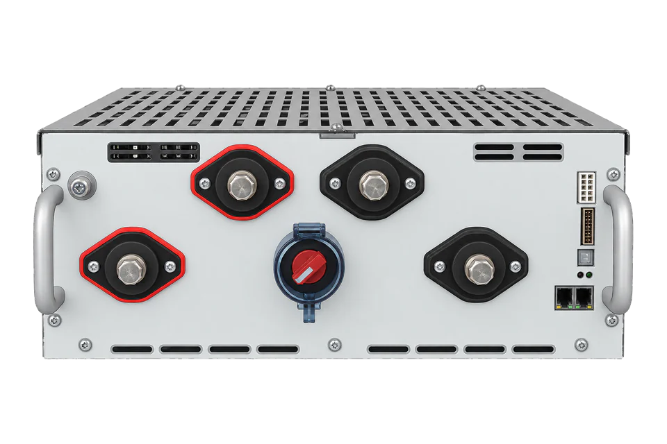
NUVG5-SSG-1500-200-1 is a G5 high-voltage BMS Stack Switchgear variant, rated 1,500V DC and 200A with a 200A fuse. It combines stack-level switching and measurement with connected cell-interface modules. Its SunSpec interface can report battery limits and conditions, but the single supported Modbus TCP connection makes network ownership a critical part of integration.
- Modbus TCP
High-voltage battery management switchgear
Compatibility
Documented local Modbus TCP interface
Nuvation publishes its SunSpec Draft 3 monitoring map and links the associated workbook. The examples below provide a best-effort Edge client starting point for SOC, DC voltage and current. Use the assigned monitoring connection; these documented reads are not physical-site qualification.
Exact NUVG5-SSG-1500-200-1 under product manual NE-PM-011 rev2.1, Faraday Update 2. CI-24 deployment is described here, not the separate preliminary CI-36 documentation. Monitoring must not displace an existing safety/control client or write contactor commands, heartbeat settings or protection thresholds.
Connect it with
-
Gateway ZGW-20From €899 ex VAT Configure Gateway
-
Evaluation Gateway on a Raspberry Pi Edge with one device licensedFree Set up Evaluation Gateway on a Raspberry Pi

Only when the system owner has assigned the single connection to monitoring
- Modbus
- Edge
- Platforms
Models
| Models | Interface | Route into Edge |
|---|---|---|
| NUVG5-SSG-1500-200-1 | 1500V DC, 200A Stack Switchgear with 200A fuse | Record the exact switchgear configuration and Faraday software version. |
| Other 1500V current/fuse options and 350V/1000V switchgear | Distinct voltage, current and protection ratings | Do not treat the family name as an interchangeable electrical specification. |
| CI-24 and preliminary CI-36 cell interfaces | Separate deployment documentation and limits | This guide uses the released CI-24 manual; do not inherit its chain limits for CI-36. |
Specifications
- Exact variant
- NUVG5-SSG-1500-200-1: 1500V DC, 200A, 200A fuse1
- Protocol endpoint
- TCP 502; one simultaneous Modbus connection1
- Address regions
- Unit ID 1: SunSpec at 40000; unit ID 2: configurable points at 01
- Implemented models
- SunSpec Energy Storage Draft 3 common, 801, 802 and 8031
- CI-24 chain
- Up to 32 modules, with cell scan rate falling as chain length increases1
- Environmental limits
- -20 to +60 °C; operational humidity 5–85%; operating altitude up to 2000m1
Interface
Documented measurements and integration boundaries for G5 SSG 1500-200-1.
- Common-model manufacturer, model, serial and firmware identity.
- Model 801 battery state of charge, heartbeat and operational status.
- Model 802 battery voltage and charge/discharge current limits, with their associated scale factors.
- Model 803 stack/string voltage, current and temperature statistics, respecting configured repeating blocks.
- Warnings, faults, unimplemented-point sentinels and communication freshness.
- Battery charge/discharge limits are BMS constraints, not a command to dispatch the storage plant.
Assessment
NUVG5-SSG-1500-200-1 with Faraday Update 2; observation only, preserving control ownership.
- InteroperabilityWell supported
- The manual documents SunSpec model IDs, unit-ID regions, addressing and complete read examples. Dynamic discovery and configuration remain necessary.1
- AccuracySupported with conditions
- Cell, stack and battery models distinguish measurement boundaries and expose limits, fault states and unimplemented values. The BMS is not a revenue-energy meter.1
- SecuritySupported with conditions
- Operator Interface password protection is documented separately from Modbus. Monitoring must restrict network access and avoid all protection and contactor writes.1
- ReliabilitySupported with conditions
- Self-check, service lockout and watchdog behavior are documented. The single-client limit means careless polling can conflict with the existing control architecture.1
- RuggednessSupported with conditions
- Temperature, humidity, altitude and mechanical-test limits are documented; enclosure suitability still belongs to the complete battery installation.1
- ScalabilitySupported with conditions
- Up to 32 CI-24 modules are supported with explicit scan-rate reductions. Repeating model blocks and one TCP connection constrain client design.1
Setup
Read BMS identity, SOC, voltage and current
A four-register identity read derived from the manufacturer’s common-model table and polling example. It establishes the map entry point, not electrical readiness.
- Endpoint
- Configured BMS IP, TCP 502, unit ID 1; exclusive assigned connection
- Function and start
- FC03 holding registers; PDU address 40000 decimal = 0x9C40
- Request PDU
- 03 9C 40 00 04
- Expected data bytes
- 53 75 6E 53 00 01 00 42
- Decode
- 0x53756E53 is SunS; model ID 1; common block length 66
- Next header
- 40002 + 2 + 66 = 40070; the cited firmware places model 801 here
- Unavailable data
- Signed16 0x8000, unsigned16 0xFFFF, signed32 0x80000000 and unsigned32 0xFFFFFFFF are unimplemented values
- State of charge
- For the documented Draft 3 layout, model 801 header is 40070 with L=22. SoC is U16 at 40081 (header+11); SoC_SF is S16 at 40092 (header+22). FC03 requests: 03 9C 91 00 01 and 03 9C 9C 00 01. Synthetic raw 1C DF = 7391 and SF FF FE = -2 give 73.91%. Read the actual scale factor; the payload is an illustrative decoder fixture.
- External DC voltage
- Model 802 header follows at 40094 with L=20. Vol is U16 at 40105 (header+11), Vol_SF is S16 at 40113 (header+19). FC03 requests: 03 9C A9 00 01 and 03 9C B1 00 01. Synthetic raw 14 50 = 5200 with SF -1 gives 520.0 V. This is the external battery-system DC bus measurement, not a cell voltage or an AC reading.
- Signed total DC current
- Model 803 header is 40116 in this layout. BTotDCCur is S16 at 40127 (header+11); BCurrent_SF is S16 at 40132 (header+16). FC03 requests: 03 9C BF 00 01 and 03 9C C4 00 01. Synthetic FF 83 = -125 with SF -1 gives -12.5 A. Nuvation documents negative current for charging and positive for discharging. Preserve 0x8000 as unavailable; limits MaxBatACha/MaxBatADischa are constraints, not measured current.
Acceptance: These are best-effort starting reads from the documented Faraday Update 2 / Draft 3 layout. Discover the installed model boundaries and compare observations with the BMS Operator Interface. Keep the existing connection owner and control settings; successful monitoring does not authorize contactor operation or battery dispatch.
-
Establish connection ownership first
Confirm the exact switchgear part number, configured cell-interface chain and Faraday software version. Identify the existing PCS/EMS controller. Only one Modbus TCP connection is supported, so do not attach an additional polling client to a production control endpoint.
-
Choose an observation path that preserves control
If another controller already owns the connection, use its approved data-sharing interface. If direct monitoring is appropriate, have the system owner assign the connection and confirm the existing safety configuration. Do not disable a controller heartbeat or change protection logic to make polling work.
-
Read the SunSpec signature and common header
Use the BMS IP, TCP 502 and unit ID 1. Read four holding registers starting at PDU address 40000. Validate the SunS signature, common-model ID and length, then read the model and firmware identity before proceeding.
-
Discover model boundaries and full point widths
Walk model IDs and lengths to the end model and bind each point to the installed model revision. Read all words of multi-register points together. Unit ID 2 belongs to a separately configured map and must not be interpreted as the same SunSpec addresses.
-
Validate observations without issuing commands
Start with SoC 40081 and scale 40092, DC voltage 40105 and scale 40113, and total DC current 40127 and scale 40132 in the documented Draft 3 layout. Apply signed base-10 factors and preserve unimplemented values. Read BMS heartbeat 40086 and two-word event field 40101 for freshness and status. Compare with the Operator Interface; faster polling does not create newer measurements.
Common questions
- Can Edge poll alongside an existing EMS?
- Not as an independent second TCP client on this endpoint: the manual specifies a single Modbus connection. Preserve the control owner and obtain data through it, or agree a separate supported architecture before integration.1
- Does the Operator Interface password protect Modbus?
- The manual separately describes a password-protected Operator Interface and a read/write Modbus service. Do not infer that the web-interface lock authenticates register requests. Restrict network access and keep monitoring commands read-only.1
- Why can a valid Modbus response contain no usable reading?
- Unimplemented SunSpec points return type-specific sentinel values in an otherwise valid response. The manual also identifies unimplemented fields, including model 802 cycle count and state of health. Do not convert these to large numbers or zero.1
Related devices
Sources
- G5 High-Voltage BMS product manual NE-PM-011 rev2.1, Faraday Update 2 (opens in a new tab) (PDF)
- G5 BMS technical resources and firmware-specific documents (opens in a new tab)
- Nuvation-linked MESA Energy Storage models Draft 3 workbook (opens in a new tab)
Further reading
Product names and trademarks belong to their owners. Publication does not imply endorsement or a commercial relationship.