Saia-Burgess Controls (SBC) ALE3 Modbus
Power and energy meter
The ALE3D5FD10 is the Modbus RTU version of the Saia-Burgess Controls ALE3 three-phase meter: direct connection up to 65 A, two tariffs, and an RS-485 port on terminals D and /D. It is sold as ALE3D5FD10C2A00 (standard) and ALE3D5FD10C3A00 (MID). SBC numbers its 52 registers from one, so register R goes on the wire as R minus 1. Voltage, current, power and cos phi are single 16-bit registers with fixed multipliers, and the tariff energy counters are 32-bit values sent high register first in hundredths of a kWh.

Compatibility
Compatible with EpiSensor Edge over Modbus RTU
Saia-Burgess Controls documents Modbus RTU over RS-485 for the ALE3D5FD10 and publishes its register table with numbering, lengths, multipliers and word order. The meter is compatible with EpiSensor Edge over Modbus RTU, through a ZMB-31 Modbus Interface or the Gateway's serial port.
ALE3D5FD10C2A00 and ALE3D5FD10C3A00, using the register table in datasheet PP26-527 ENG05 and user guide 4 319 5113 0 I as the starting point. Compare the first read with the meter display. The bidirectional ALE3B5FD00, the ALE3D5FD10C3A44 (KV44, its own user guide) and the M-Bus and S-Bus ALE3 versions are outside this guide. Read-only monitoring.
Connect it with
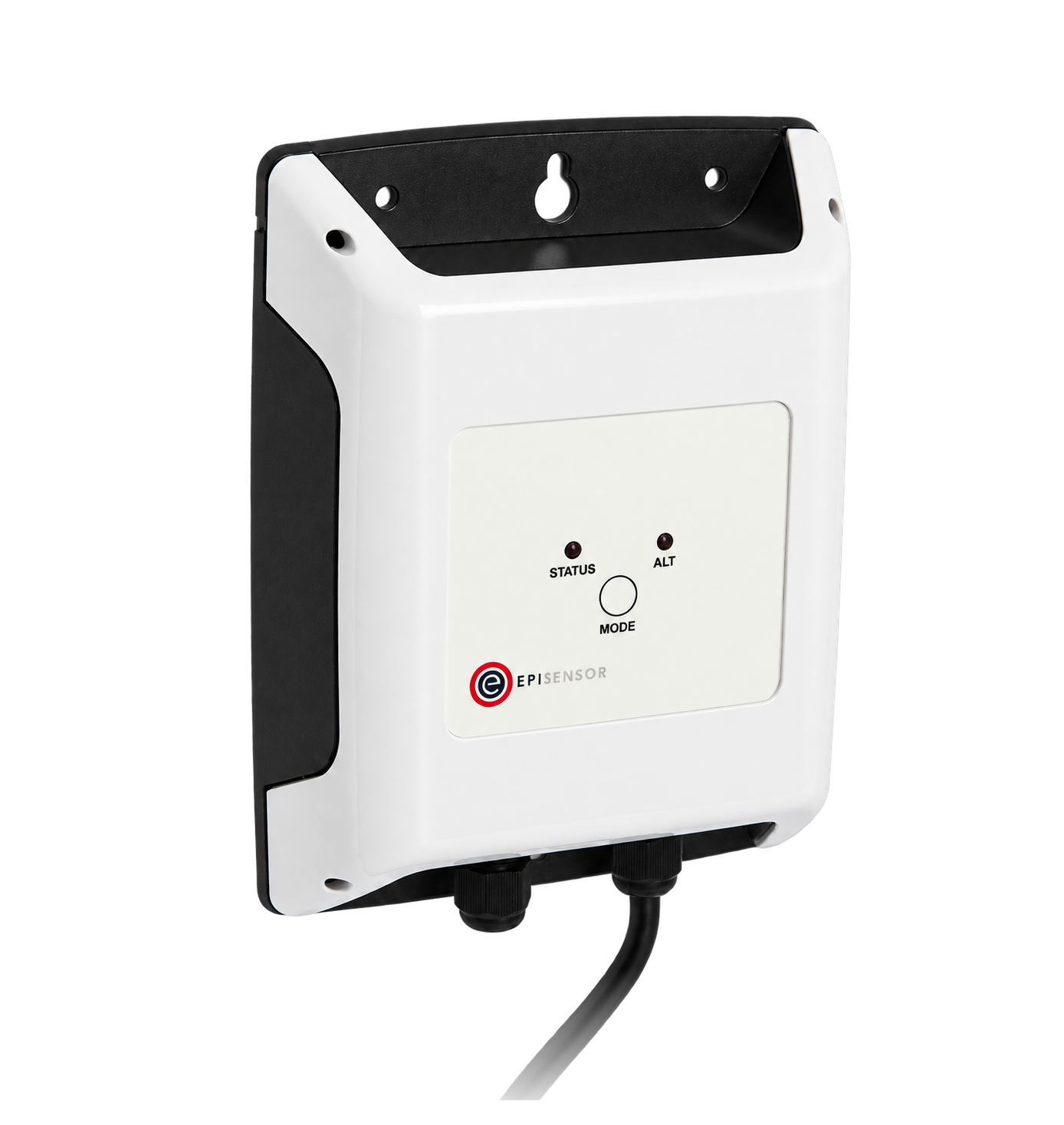
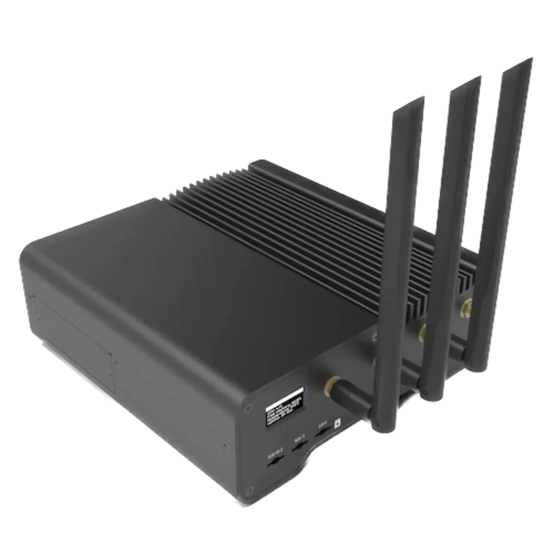
When the meter is in a board away from the Gateway
- Modbus
- Wireless
- Edge
- Platforms
When an RS-485 serial interface is available at the Gateway
- Modbus
- Edge
- Platforms
Models
| Models | Interface | Route into Edge |
|---|---|---|
| ALE3D5FD10C2A00 (standard) | Direct connection, Iref 10 A, Imax 65 A; RS-485 Modbus RTU on D and /D; tariff input E1/E2 | Read the register table with FC03 on the serial path. Register 12 reads C2. |
| ALE3D5FD10C3A00 (MID) | The same meter and register table with MID approval | Same read path. Register 12 reads C3. |
| ALE3B5FD00 (bidirectional) | Shares the user guide and register numbers, but registers 28 to 35 hold consumption and feed-back counters instead of tariffs 1 and 2, and there is no tariff input | Outside this guide. Do not reuse the tariff labels for an ALE3B5FD00. |
Specifications
A four-wire, three-phase meter for direct connection, with backlit LCD, two tariff registers switched by a ripple control signal on E1 and E2, and resettable partial counters per tariff. The Modbus port reports per-phase voltage, current, active and reactive power and cos phi as well as the energy counters.12
- Order codes
- ALE3D5FD10C2A00 (standard) and ALE3D5FD10C3A00 (MID).1
- Current
- Iref 10 A, Imax 65 A, starting current 40 mA, Imin 0.5 A.1
- Accuracy and approval
- Class B to EN 50470-3 and class 1 to IEC 62053-21. MID applies to the ALE3D5FD10C3A00 only.12
- Modbus RTU
- RS-485, RTU to the IDA specification. 4800, 9600, 19200, 38400, 57600 or 115200 bit/s, detected automatically. Even or odd parity with 1 stop bit, or no parity with 2 stop bits, detected automatically. Address 1 to 247, set on the display.12
- Bus
- Twisted, shielded 2 × 0.5 mm² cable up to 1200 m. Up to 247 meters, with a repeater above 128. No terminating resistor in the meter. Typical response 5 character times, maximum 60 ms.1
- Data timing
- Communication starts 30 s after power-on and needs L1 connected. Values refresh every 10 s, so poll one meter no faster than every 10 s.12
- Other interfaces
- Tariff control input E1/E2 for a ripple control receiver; test LED at 1000 imp/kWh.1
- Mounting
- 35 mm DIN rail (EN 60715 TH35), 70 mm wide and 62 mm deep in the dimension drawing, for installation cabinets only. Main terminals 1.5 to 16 mm², control terminals up to 2.5 mm².12
- Environment
- Operation -25 to +55 °C, storage -30 to +85 °C, humidity up to 75% without condensation, mechanical class M2, electromagnetic class E2, protection class II.1
Interface
Documented measurements and integration boundaries for ALE3 Modbus.
- Register numbers are one-based: register R is sent as PDU address R - 1. Read with FC03 only, and no more than 20 registers per request.
- L1, L2 and L3 voltage at registers 36, 41 and 46 (PDU 35, 40 and 45): one register each, whole volts.
- L1, L2 and L3 current at registers 37, 42 and 47: one register each, multiplier 0.1 A.
- L1, L2 and L3 active power at registers 38, 43 and 48, total active power at register 51: one register each, multiplier 0.01 kW.
- L1, L2 and L3 reactive power at registers 39, 44 and 49, total reactive power at register 52: one register each, multiplier 0.01 kvar.
- cos phi for L1, L2 and L3 at registers 40, 45 and 50: one register each, multiplier 0.01.
- Tariff 1 total energy at registers 28 to 29 and tariff 2 total energy at registers 32 to 33: 32-bit, high register first, multiplier 0.01 kWh.
- Tariff 1 and tariff 2 partial energy at registers 30 to 31 and 34 to 35: the same format, and resettable, so log the total counters.
- Active tariff at register 27 (0 is tariff 1, 4 is tariff 2) and phase error flags at register 25 (1 L1, 2 L2, 4 L3, added together).
- Identity: firmware version at register 1, type code at registers 7 to 14 (register 12 reads C2 or C3), hardware version at register 15, serial number at registers 16 to 18.
Assessment
ALE3D5FD10C2A00 and ALE3D5FD10C3A00, using the register table in datasheet PP26-527 ENG05 and user guide 4 319 5113 0 I as the starting point. Compare the first read with the meter display. The bidirectional ALE3B5FD00, the ALE3D5FD10C3A44 (KV44, its own user guide) and the M-Bus and S-Bus ALE3 versions are outside this guide. Read-only monitoring.
- InteroperabilityWell supported
- SBC documents Modbus RTU on RS-485, the supported function codes, the register numbering rule, register lengths, multipliers, word order for double registers and the exception responses, with worked decoding examples.12
- AccuracySupported with conditions
- Class B (1%) metering with per-phase voltage, current, active and reactive power and cos phi, and two tariff energy counters at 0.01 kWh. Voltage is reported in whole volts, there is no frequency register, and values refresh only every 10 s.1
- SecurityNot yet assessed
- The register table accepts FC16 writes to the Modbus address and the partial counters, and the documents describe no access control on the Modbus port.1
- ReliabilitySupported with conditions
- Settings are stored in EEPROM on voltage loss, a status register flags a failed request and an error register reports phase errors. The interface depends on phase 1 and needs 30 s after power-on, so treat failed reads as missing data.12
- RuggednessSupported with conditions
- Rated -25 to +55 °C, M2 and E2, humidity up to 75% without condensation, protection class II, with surge and burst immunity of 1 kV on the Modbus interface. For installation cabinets only.12
- ScalabilitySupported with conditions
- Up to 247 meters per bus over 1200 m, with a repeater above 128 meters. Each meter answers at most 20 registers per request and refreshes every 10 s, which sets the polling budget on a busy bus.1
Setup
Read L1 voltage from register 36
Datasheet PP26-527 ENG05 and user guide 4 319 5113 0 I list URMS phase 1 at register 36, one register, unit V, with the example 230 = 230 V. Use that table as the starting point and compare the result with the display.
- Request
- 01 03 00 23 00 01 75 C0: Modbus address 1, FC03, PDU address 0x0023, one register, RTU CRC.
- Address convention
- SBC numbers registers from one and states that register R is sent as R - 1. Register 36 is therefore zero-based PDU address 35 (0x0023). A client that asks for one-based register numbers takes 36, or 40036 in five-digit holding-register notation.
- Synthetic response
- 01 03 02 00 E6 39 CE: two data bytes, 00 E6.
- Decode
- 0x00E6 is 230. The voltage registers carry whole volts with no multiplier, so the reading is 230 V.
- Acceptance
- Keep the point when it agrees with U(V) for L1 on the meter display at the same time. If it does not, check the address, the minus-one numbering and the order code before adding more points.
Acceptance: The response bytes are a synthetic decoder check, not a captured meter reply. A real reply must agree with the display before current, power and energy points are enabled.
-
Identify the meter
Read the order code on the front label: ALE3D5FD10C2A00 or ALE3D5FD10C3A00. Other ALE3 order codes, including the bidirectional ALE3B5FD00 and the KV44 version ALE3D5FD10C3A44, are not covered here.
-
Read the Modbus address
Hold the right-arrow key for 3 s to show the address screen; the down key adds 10 and the right key adds 1, so leave it unchanged if the address is already planned. The display returns to the start screen on its own.
-
Wire and terminate the RS-485 pair
Connect the bus to D and /D and fit terminating resistors at the ends of the bus, since the meter has none. Check that L1 and N are connected: the interface works only with phase 1 present, and is ready 30 s after power-on.
-
Make one voltage read
Send FC03 to PDU address 35 (register 36) for one register, as in the worked read below, and compare the result with L1 voltage on the display.
-
Add the points you need
Add current, power and the two tariff total counters from the same table, poll each meter every 10 s or slower, and keep FC16 writes out of the polling configuration.
Common questions
- Do I send register 36 as address 36?
- No. SBC states that register R is numbered R - 1 when transmitted, so register 36 goes on the wire as 35 (0x0023). Tools that take one-based register numbers do the subtraction for you; enter 36 there, not 35.12
- How do I decode the energy counters?
- Each total counter is two registers, high register first, in hundredths of a kWh. SBC's own example is high 13 and low 60383: 13 × 65536 + 60383 = 912351, which is 9123.51 kWh. Consumption across both tariffs is tariff 1 total (registers 28 to 29) plus tariff 2 total (registers 32 to 33).1
- How often can Edge poll the meter?
- SBC refreshes the values every 10 s and asks for at least 10 s between reads of the same data. A request for more than 20 registers returns exception 02, so split a long block into two reads.12
- Which registers can be written?
- The Modbus address at register 24 (not by broadcast) and the partial counters at registers 30 to 31 and 34 to 35, which reset when 0 is written to both registers in one FC16 message. A monitoring configuration should read with FC03 only.1
Related devices

Sources
- Datasheet PP26-527 ENG05 (05.2017): 3 phase energy meters with integrated Serial Modbus interface, ALE3 (opens in a new tab) (PDF)
- Mounting instructions and user guide 4 319 5113 0 I (11.2025): ALE3 with Modbus, unidirectional ALE3D5FD10 and bidirectional ALE3B5FD00 (opens in a new tab) (PDF)
- Axx3 (3-ph. ModBus) energy meters support page (opens in a new tab)
Further reading
Product names and trademarks belong to their owners. Publication does not imply endorsement or a commercial relationship.