Wired M-Bus segment calculator

Check a wired M-Bus segment against the master’s unit-load capacity, the voltage left at the farthest meter and the cable capacitance allowed at its baud rate.

M-Bus and pulse Updated Free, no sign-up

Meters

From the meter datasheet; usually 1

UL
Master

Master sizes

UL

Mark (idle) level

V
Cable
Baud rate

All branches together

km

Both conductors, out and back

Ω
nF/km
More options
UL
nF

30 meters on one segment

1 of 3 limits exceeded

Bus current with the reserve
60 mA
Most meters this master takes
50
  • Pass: Master capacity40 unit loads with the reserve, of 6020 UL spare
  • Pass: Voltage at the farthest meter31.56 V, above the 24 V target7.56 V spare
  • Fail: Bus capacitance at 9,600 baud115 nF of 100 nF. Lower the baud rate or split the cable.15 nF over

A planning estimate from the OMS installation guidance. Measure the bus voltage at the farthest meter when commissioning.

How it’s calculated
  1. Load = devices × UL + reserve=30 × 1 + 10=40 UL
  2. I = load × 1.5 mA=40 × 1.5=60 mA
  3. Vfar = Vmaster − I × R=36 − 0.06 × 74=31.56 V
  4. C = length × Ccable + devices × Cdevice=100 + 15=115 nF

Choose the devices that read these meters.

Build a system

30 meters with 40 unit loads in all, reserve included, draw 60 mA and leave about 31.56 V at the farthest meter. The bus capacitance is 115 nF of the 100 nF allowed at 9,600 baud.

Tip: Capacitance, not current, usually limits a long M-Bus run. Dropping from 9,600 to 2,400 baud allows more cable on the same segment.

How to size a wired M-Bus segment

A wired M-Bus master powers every meter on its segment, so each segment has three budgets. The master must supply every unit load. The cable resistance must leave at least 24 V at the farthest meter. The capacitance of the cable and the meters must stay under the limit for the baud rate. Thirty 1 UL meters on a 60 UL master, with 1 km of J-Y(St)Y 2×2×0.8 mm cable at 2,400 baud, pass all three.

Unit loads

ULdesign = N × ULdevice + ULreserve ≤ ULmaster

One unit load (UL) is an idle current of up to 1.5 mA. OMS TR02 section 5.1.5 puts every meter in a class from 1 to 4 UL, so no meter draws more than 6 mA, and the class must appear on the datasheet and on the meter. Masters are rated in UL; 20, 60 and 250 UL are common sizes. Keep a reserve for meters added later. The calculator counts the reserve in the current and the voltage drop, but not in the capacitance.

Voltage at the farthest meter

Ufar = Umark − Iidle × Rsegment

OMS TR02 section 5.1.1.4 requires at least 24 V DC mark voltage at the terminals of every meter. The calculator passes the whole idle current through the full resistance to the farthest meter, as if every meter sat at the far end. That is the worst case. Enter the loop resistance, both conductors out and back. The OMS reference cable has about 37 Ω per conductor per km, so 1 km of it is about 74 Ω. The mark voltage on a datasheet is usually the no-load figure: add the internal resistance of the master to the cable resistance, or enter the loaded output voltage.

Capacitance

Ctotal = Ltotal × Ccable + N × Cdevice

Add up every cable run on the segment, branches included, not only the run to the farthest meter. OMS TR02 section 5.1.1.4 limits the total to 1,000 nF at 300 baud, 400 nF at 2,400 baud and 100 nF at 9,600 baud. On 100 nF/km cable that is 10 km, 4 km and 1 km. EN 13757-2 limits the input capacitance of each meter to 0.5 nF, so thirty meters add up to 15 nF.

On long segments the capacitance limit usually fails first. Thirty meters on 1 km of the OMS reference cable use 115 nF of the 400 nF allowed at 2,400 baud, but lose only 4.44 V of the 12 V between a 36 V master and the 24 V minimum. The two limits measure different lengths. Resistance depends on the distance to the farthest meter. Capacitance depends on all the cable added together. A star layout keeps the first short but adds cable, so it uses up capacitance faster than a line.

Lower the baud rate before you split a segment. 2,400 baud allows four times the capacitance of 9,600 baud. OMS TR09 gives a read time of about 2 s per meter at 2,400 baud and 1 s at 9,600 baud, so thirty meters take about 60 s instead of 30 s. That is short against a 15-minute read interval.

The calculation checks the idle state only. A meter that replies adds 11 to 20 mA, which through 74 Ω drops up to 1.48 V more while it transmits. The master treats a current step above 50 mA as a collision, which is what several meters replying at once produce. Duplicate primary addresses cause this; the M-Bus address planner finds them. A faulty meter that draws current continuously pulls the voltage down for every meter on the segment.

M-Bus segment design examples

Thirty heat meters on a 60 UL master

Thirty 1 UL meters plus a 10 UL reserve is 40 UL. That draws 60 mA and leaves 20 UL spare on the master. The 74 Ω is the loop resistance of 1 km of J-Y(St)Y 2×2×0.8 mm cable. 60 mA through 74 Ω drops 4.44 V, so the farthest meter sees 31.56 V, 7.56 V above the 24 V minimum. The cable adds 100 nF and the meters 15 nF, a total of 115 nF against 400 nF at 2,400 baud. The segment is within the limits.

30 meters on one segment Within the limits Open in the calculator
Doubling the meters on the same master

Sixty meters and the 10 UL reserve need 70 UL, which is 10 UL more than the master supplies. The other two checks pass: 105 mA through 74 Ω still leaves 28.23 V at the far end, and 130 nF is well under 400 nF. That is 1 of 3 limits exceeded, and only the master is short. Use a 250 UL master, or split the meters across two 60 UL segments.

60 meters on one segment 1 of 3 limits exceeded Open in the calculator

The same segment at 9,600 baud

At 9,600 baud the limit falls to 100 nF, and the 115 nF segment is 15 nF over it. That is 1 of 3 limits exceeded. With thirty meters on this cable, 9,600 baud allows only 0.85 km of cable in total. Stay at 2,400 baud: the segment then has 285 nF spare and the thirty meters still read in about a minute.

30 meters on one segment 1 of 3 limits exceeded Open in the calculator

M-Bus cable length and baud rate

Total capacitance of thirty meters at 0.5 nF each on cable of 100 nF/km, against the OMS TR02 limit at each baud rate.

Total cable (km)Capacitance (nF)At 300 baudAt 2,400 baudAt 9,600 baud
0.2540WithinWithinWithin
0.565WithinWithinWithin
1115WithinWithinOver
1.5165WithinWithinOver
2215WithinWithinOver
3315WithinWithinOver
4415WithinOverOver
5515WithinOverOver
8815WithinOverOver

Download this table (CSV)

Questions about M-Bus segment design

How many meters can one M-Bus master drive?

Divide the UL rating of the master, less your reserve, by the UL of each meter. A 60 UL master with a 10 UL reserve takes 50 meters of 1 UL, or 25 meters of 2 UL. Primary addressing stops at 250 meters per segment. On long runs the voltage or capacitance check can fail before the UL budget does.

How long can an M-Bus cable be?

There are two limits. The capacitance limit applies to all the cable added together: with thirty meters on 100 nF/km cable, that is 9.85 km at 300 baud, 3.85 km at 2,400 baud and 0.85 km at 9,600 baud. The resistance limit applies to the distance to the farthest meter, and depends on the master voltage and the bus current. OMS TR09 table 2 gives 2,000 m for 50 meters at 2,400 baud on 0.8 mm cable, with every meter at the far end.

What voltage should an M-Bus meter see?

At least 24 V DC at its terminals in the idle state, by OMS TR02 and the commissioning table in OMS TR09. Measure it at the farthest meter with no communication on the bus, on a multimeter range of at least 50 V DC. The master should give between 30 and 42 V DC; its datasheet gives the exact figure.

Which cable should I use for M-Bus?

The OMS reference cable is J-Y(St)Y 2×2×0.8 mm: shielded twisted pairs, 0.5 mm² conductors, at most 75 Ω/km per loop and 100 nF/km. Use one pair. A second pair in parallel halves the loop resistance but adds capacitance, so use it only when the voltage check fails and the capacitance check has room. Earth the shield at the master only. Wire in a star, line or tree, never a closed ring, and do not fit a termination resistor. The bus is polarity-independent.

Limits of this result

  • Enter the master capacity and device unit loads from their current manufacturer data; a device count alone is not a load budget.
  • The far-end voltage result is a conservative lumped-current estimate using the entered effective current-path resistance. It is not a distributed-network simulation.
  • The capacitance budget adds the entered cable and connected-device capacitance. Reserve unit loads do not add future cable or device capacitance.
  • The estimate does not verify waveform shape, rise/fall time, topology, EMC, isolation, inrush, collision handling or polling reliability.
  • Do not use the result as installation approval. Confirm the exact master, every meter or coupler, cable construction, topology and measured commissioning values.

Measure it continuously

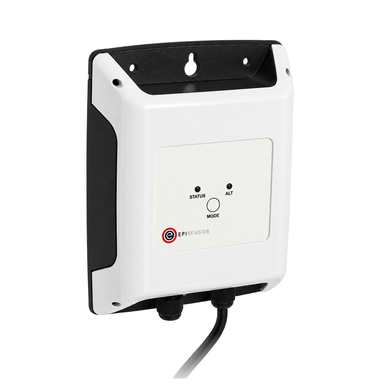
Where a single meter sits far from the rest, a ZHM reads that one wired M-Bus meter locally and sends its data to the Gateway over the wireless mesh, instead of extending the segment.

Related guides

Sources

  1. Technical Report 02: Wired M-Bus (opens in a new tab) (PDF) Open Metering System Group, Version 2.0.3 · 2023-03-29
  2. Technical Report 09: Guide for Wired M-Bus Installations (opens in a new tab) (PDF) Open Metering System Group, Version 1.0.3 · 2022-05-27