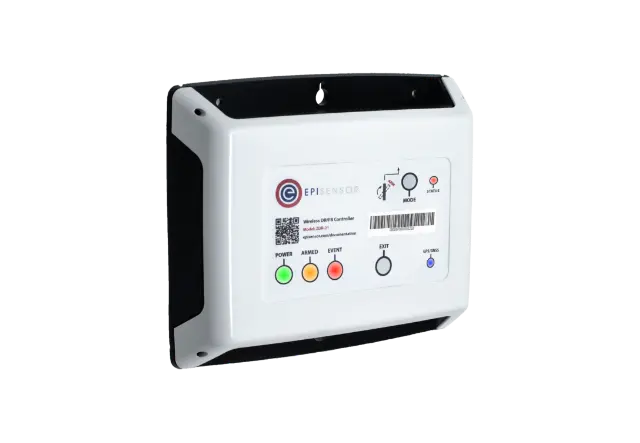
Product / ZPC-10, ZPC-20
EpiSensor’s ZPC Pulse Counter is intended to interface with sensor products which produce a dry contact (relay) or open collector output. The ZPC reports the information through the wireless sensor network to the Gateway.
The ZPC Pulse Counter interfaces with an existing meter that provides a pulsed output (gas or water flow, power consumption, etc.). The ZPC reports data in pulses and users or 3rd party software systems can interpret these values and convert to the appropriate Units of Measure for the sensor. The ZPC-10 variant is battery powered, and the ZPC-20 is a mains powerd version.
Pulse Output Installation
The pulse wires are fed through the enclosure’s M10 gland and connected to the 2 pin terminal block taking note of the positive and negative terminals. Dry pulse outputs are not polarity sensitive.
For more technical information regarding compatible pulse inputs, please see the ZPC-10/ZPC-20 datasheet.
Electrical Installation
The ZPC-20 is a mains powered device – the voltage input lead on the ZPC-20 is colour coded to conform to European CENELEC standards. The CENELEC standard insulation colours are as follows:
- L1/Live – Brown
- N – Blue
Important Note: The ZPC-20 should be connected via a switched junction box and breaker to protect the cable. Also, please ensure that the live connection is made on the same circuit as the neutral connection where residual-current devices (RCD’s) are used.
Installation should be carried out only by personnel qualified in the installation of electrical equipment. All parts of the circuit within the enclosure must be considered to be at dangerously high mains voltage when the unit is connected to a mains voltage source.
Mounting Instructions
The ZPC-10 is housed in a waterproof polycarbonate enclosure with a cable gland at the bottom for the pulse input. The ZPC-20 is housed in the same enclosure, but includes mains voltage input cables.
The ZPC requires 2 screws for mounting. These screws can be preinstalled on a vertical surface spaced 120mm vertically apart. The head of the screw should be less than 8.5mm in diameter and the screw thickness should be less than 4.5mm. The screws should be left unscrewed by more than 5mm before installing the enclosure.
Battery Life
The following table estimates battery life for the ZPC-10. There are other environmental factors that this table does not take into account, and the calculations are made assuming the node is not logging data for long periods of time.
Reporting Interval |
Estimated Battery Life |
---|---|
1 minute |
3 months |
15 minutes |
4 years |
30 minutes |
6 years |
60 minutes |
10 years |
Sensors
The following is a list of all sensors available on the ZPC. The reporting mode, reporting interval and logging enabled columns refer to the factory default settings, these settings can be configured from the Gateway.
Sensor ID |
Name |
Description |
Reporting Mode |
Reporting Interval |
Logging Enabled |
---|---|---|---|---|---|
450 |
Pulse Count |
Incrementing Pulse Value |
OFF |
15 |
Yes |
451 |
Reset Status |
Indicates any reset conditions on the node. 1 = Power, 3 = Wdog, 10 = Software |
Interval Only |
1440 |
Yes |
462 |
Interval Pulse Count |
Pulse Count since last reported value |
Snap to Clock |
15 |
Yes |
4096 |
Battery Level |
On Battery Powered Pulse Counters Only |
Snap to Clock |
1440 |
Yes |